AS/NZS 1125 Armoured Control Cable 0.6/1kV
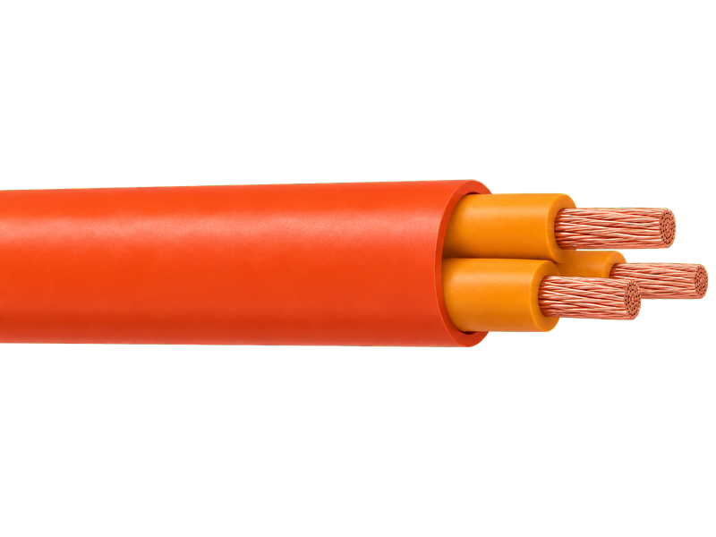
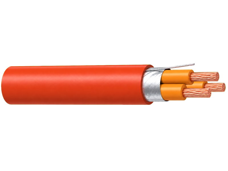
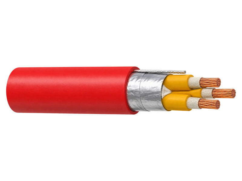
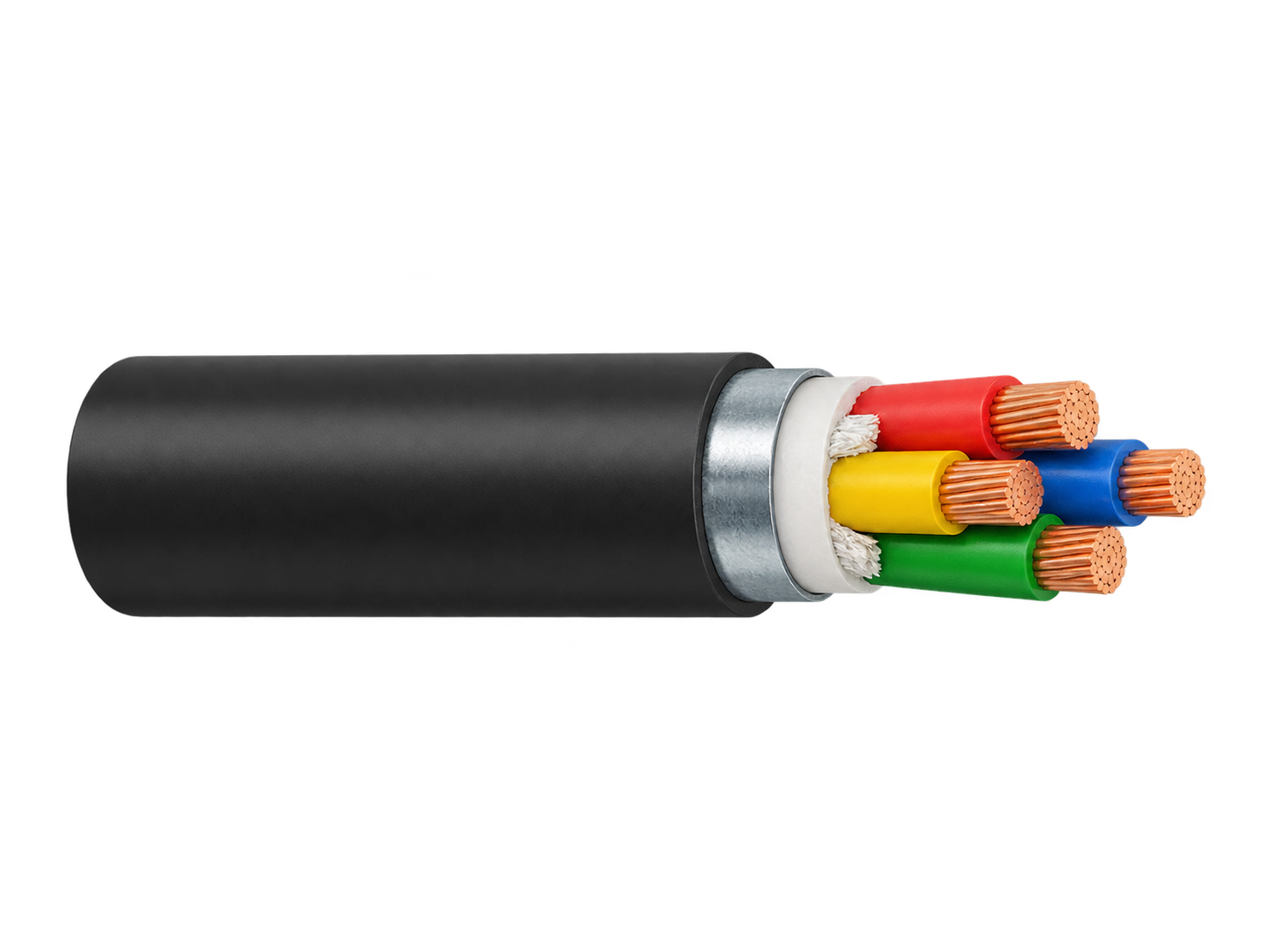
AS/NZS 1125 Armoured Control Cable is a 0.6/1kV multicore-plus-earth control cable using plain annealed copper conductors in stranded constructions selected for reliable electrical performance in commercial, industrial, mining and utility control circuits. The available range uses 1.5 mm² conductors in 7/0.50 mm construction and 2.5 mm² conductors in 7/0.67 mm construction, combined with PVC V-90 insulation, PVC bedding, galvanised steel wire armour and PVC 5V-90 outer sheath. With conductor resistance, core identification and multicore assembly controlled as part of the finished cable design, the product is suitable for fixed installations where both dependable control-circuit performance and mechanical protection are required.
Conductor Construction
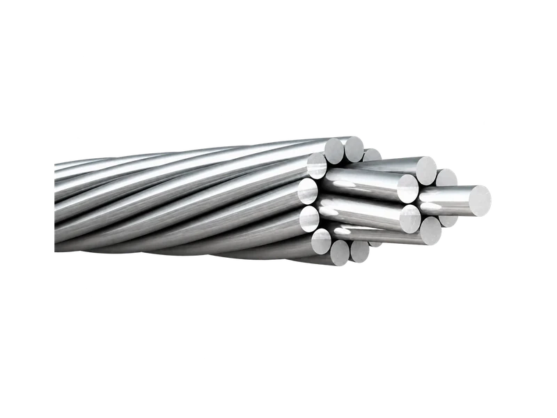
The conductor is the electrical core of the cable and directly influences resistance, voltage drop and current-carrying capability. Two conductor sizes are offered in this product range. The 1.5 mm² conductor is formed from seven 0.50 mm copper wires, while the 2.5 mm² conductor is formed from seven 0.67 mm copper wires. Both use plain annealed copper and are integrated into multicore-plus-earth cable constructions for fixed control applications.
Product Highlights
- 6/1kV multicore + earth armoured control cable.
- Plain annealed copper conductors.
- 5 mm² conductor: 7/0.50 mm stranded construction.
- 5 mm² conductor: 7/0.67 mm stranded construction.
- PVC V-90 core insulation.
- Galvanised steel wire armour for mechanical protection.
- PVC 5V-90 orange outer sheath; other colours available on request.
- Core range from 2C+E to 50C+E.
Electrical Performance
Conductor resistance decreases as conductor area increases. In this range, the maximum d.c. resistance at 20°C falls from 13.6 Ω/km for 1.5 mm² to 7.41 Ω/km for 2.5 mm². The corresponding maximum a.c. resistance at 75°C is 16.5 Ω/km and 9.01 Ω/km respectively. Lower conductor resistance supports reduced I²R loss and lower voltage drop over a given circuit length, while the final cable size must also be selected according to installation method, load current and project limits.
Typical Applications
- Commercial building control circuits.
- Industrial plant control and auxiliary circuits.
- Mining electrical systems where mechanical protection is required.
- Utility and electricity-authority control installations.
- Conduit installations.
- Direct-buried control circuits.
- Underground ducts.
- Fixed installations exposed to a risk of mechanical damage.
How to Select
- Choose the required conductor size: 1.5 mm² or 2.5 mm².
- Select the required multicore-plus-earth configuration.
- Check conductor resistance against circuit-length and voltage-drop requirements.
- Confirm the required installation method and current rating.
- Confirm armour and mechanical-protection requirements.
- Confirm sheath colour, marking and project documentation.
- State AS/NZS 1125 together with any other project-specified standards and edition requirements in the RFQ.
Technical Data
The table below presents the available finished-cable sizes using the two conductor constructions described above.
| Area (mm²) | Cores | Conductor | Insul. mm | Earth mm² | Earth Insul. mm | Bedding OD mm | Armour mm | Overall OD mm | Mass kg/km |
|---|---|---|---|---|---|---|---|---|---|
| 1.5 | 2C+E | 7/0.50 | 0.8 | 1.5 | 0.6 | 9.0 | 0.90 | 14.5 | 405 |
| 1.5 | 3C+E | 7/0.50 | 0.8 | 1.5 | 0.6 | 9.8 | 0.90 | 15.4 | 440 |
| 1.5 | 4C+E | 7/0.50 | 0.8 | 1.5 | 0.6 | 10.7 | 0.90 | 16.3 | 550 |
| 1.5 | 6C+E | 7/0.50 | 0.8 | 1.5 | 0.6 | 11.7 | 0.90 | 17.3 | 690 |
| 1.5 | 8C+E | 7/0.50 | 0.8 | 1.5 | 0.6 | 13.6 | 1.25 | 19.9 | 770 |
| 1.5 | 10C+E | 7/0.50 | 0.8 | 1.5 | 0.6 | 14.9 | 1.25 | 21.2 | 920 |
| 1.5 | 12C+E | 7/0.50 | 0.8 | 1.5 | 0.6 | 16.2 | 1.25 | 22.5 | 1010 |
| 1.5 | 15C+E | 7/0.50 | 0.8 | 1.5 | 0.6 | 17.1 | 1.60 | 23.4 | 1110 |
| 1.5 | 20C+E | 7/0.50 | 0.8 | 1.5 | 0.6 | 19.0 | 1.60 | 26.0 | 1535 |
| 1.5 | 25C+E | 7/0.50 | 0.8 | 1.5 | 0.6 | 21.7 | 1.60 | 28.7 | 1670 |
| 1.5 | 30C+E | 7/0.50 | 0.8 | 1.5 | 0.6 | 23.5 | 1.60 | 30.4 | 1840 |
| 1.5 | 40C+E | 7/0.50 | 0.8 | 1.5 | 0.6 | 26.4 | 1.60 | 34.8 | 2260 |
| 1.5 | 50C+E | 7/0.50 | 0.8 | 1.5 | 0.6 | 28.9 | 1.60 | 36.1 | 2400 |
| 2.5 | 2C+E | 7/0.67 | 0.8 | 2.5 | 0.7 | 10.0 | 0.90 | 15.6 | 210 |
| 2.5 | 3C+E | 7/0.67 | 0.8 | 2.5 | 0.7 | 10.9 | 0.90 | 16.5 | 250 |
| 2.5 | 4C+E | 7/0.67 | 0.8 | 2.5 | 0.7 | 12.0 | 0.90 | 17.6 | 285 |
| 2.5 | 6C+E | 7/0.67 | 0.8 | 2.5 | 0.7 | 13.1 | 1.25 | 19.4 | 365 |
| 2.5 | 8C+E | 7/0.67 | 0.8 | 2.5 | 0.7 | 15.3 | 1.25 | 23.0 | 455 |
| 2.5 | 10C+E | 7/0.67 | 0.8 | 2.5 | 0.7 | 16.8 | 1.25 | 23.0 | 530 |
| 2.5 | 12C+E | 7/0.67 | 0.8 | 2.5 | 0.7 | 18.3 | 1.60 | 25.2 | 605 |
| 2.5 | 15C+E | 7/0.67 | 0.8 | 2.5 | 0.7 | 19.3 | 1.60 | 26.3 | 715 |
| 2.5 | 20C+E | 7/0.67 | 0.8 | 2.5 | 0.7 | 21.5 | 1.60 | 28.5 | 950 |
| 2.5 | 25C+E | 7/0.67 | 0.8 | 2.5 | 0.7 | 24.6 | 1.60 | 31.8 | 1095 |
| 2.5 | 30C+E | 7/0.67 | 0.8 | 2.5 | 0.7 | 26.6 | 1.60 | 33.8 | 1200 |
| 2.5 | 40C+E | 7/0.67 | 0.8 | 2.5 | 0.7 | 30.4 | 2.00 | 38.8 | 1565 |
| 2.5 | 50C+E | 7/0.67 | 0.8 | 2.5 | 0.7 | 33.3 | 2.00 | 41.7 | 1925 |
Request the Complete Data Sheet
From Production to Delivery
From raw material preparation to final shipmen, every stage is caretuly controled to ensure consistent conductor quality, reliable pertormance,and sae delivery. Our roduction,
inspection, packaging, and logistics processes are managed in accordance with applicable standards and project requirements.
Production
Plain annealed copper wires are stranded to the specified conductor construction, insulated with PVC V-90, laid up with the required earth conductor, bedded, armoured with galvanised steel wire and finished with a PVC 5V-90 outer sheath.
Inspection
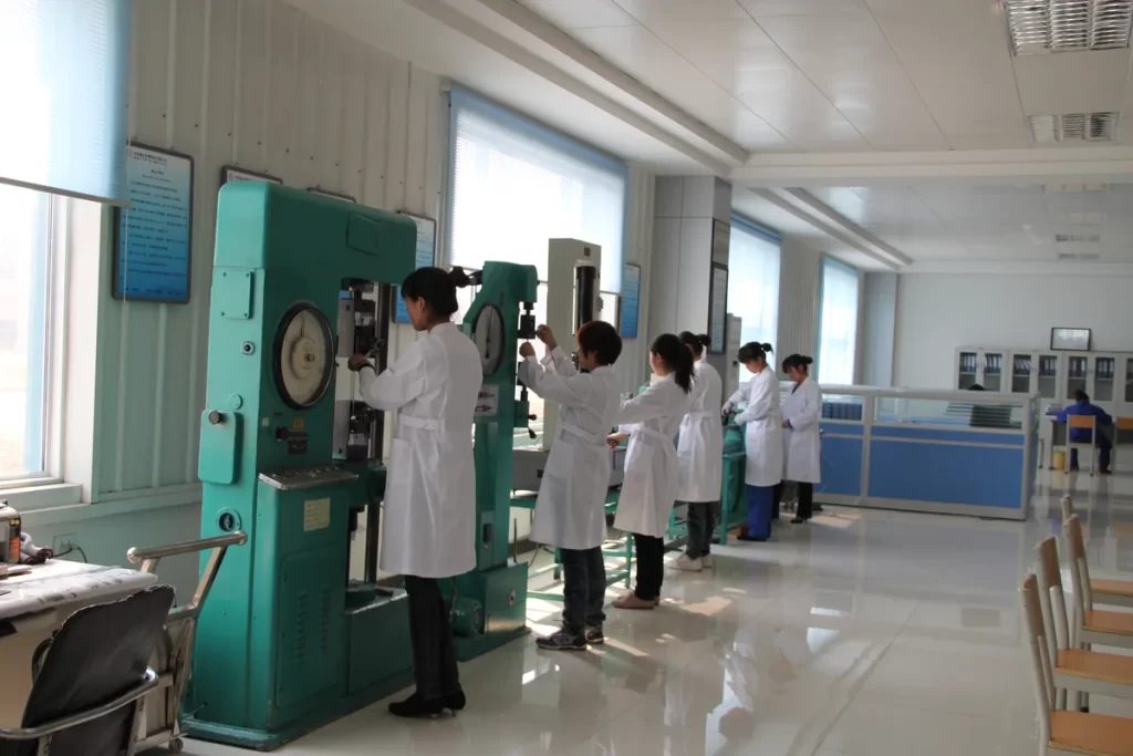
Inspection covers conductor construction, conductor resistance, insulation condition, core identification, armour integrity, overall dimensions and finished-cable electrical requirements against the approved technical schedule.
Packaging
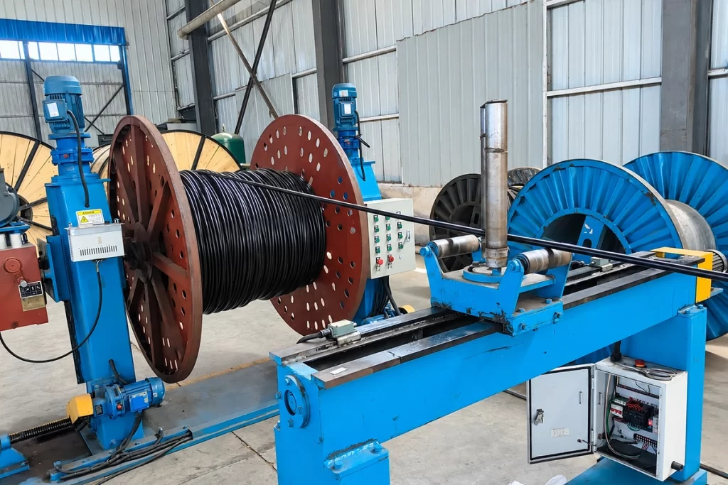
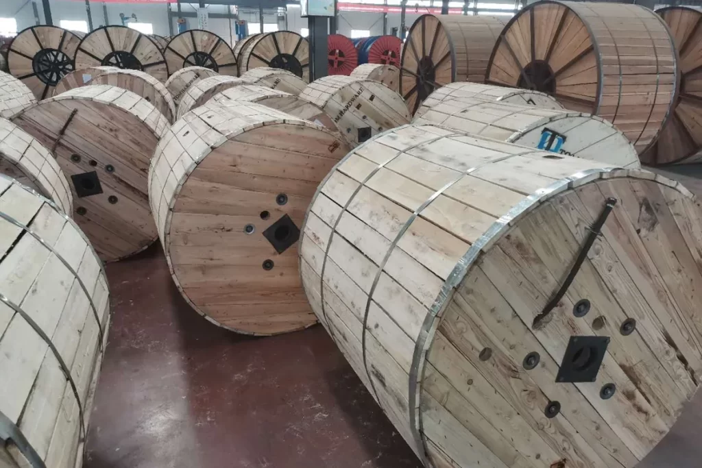
Finished cables are wound onto suitable drums according to ordered size and length. Cable ends are secured and protected, and drum identification can include cable type, conductor size, core count, length and project reference.
Shipping
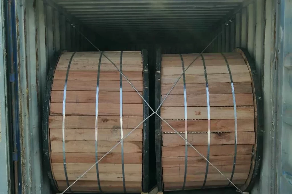
Before shipment, drums and technical documents are checked against the order and packing list. Inspection records, test documentation and product identification can be prepared according to project requirements.
Frequently Asked Questions
What is AS/NZS 1125 Armoured Control Cable?
It is a 0.6/1kV multicore-plus-earth armoured control cable using plain annealed copper conductors, PVC insulation, steel wire armour and PVC outer sheath.
What conductor sizes are available?
The available range shown here includes 1.5 mm² and 2.5 mm².
What does 7/0.50 mean?
It means seven copper wires, each 0.50 mm in nominal diameter, stranded to form the 1.5 mm² conductor.
What is the maximum DC resistance of 1.5 mm²?
13.6 Ω/km at 20°C.
What is the maximum DC resistance of 2.5 mm²?
7.41 Ω/km at 20°C.
Request for Free Consultation
Contact Information
Send us your cable requirements and our team will respond quickly with product recommendations, technical support and quotation details.