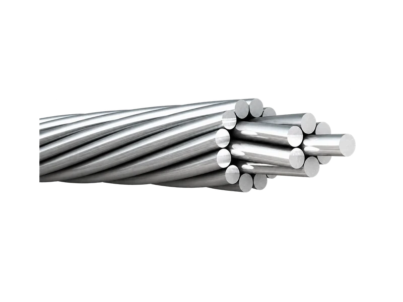
AAAC conductor selection guide
AAAC (All Aluminum Alloy Conductor) is widely used in overhead transmission and distribution systems where a combination of electrical conductivity, mechanical strength and corrosion resistance is required. Selecting the correct AAAC conductor requires consideration of conductor size, alloy grade, tensile strength, current-carrying capacity, span length, environmental conditions and applicable standards such as IEC 61089, ASTM B399 and BS EN 50182.Use this AAAC conductor selection guide.
Key Takeaways
- AAAC is commonly manufactured from aluminum alloy such as 6201.
- It provides higher mechanical strength than AAC while maintaining relatively low weight.
- AAAC is suitable for overhead transmission and distribution lines, especially in corrosive environments.
- Main selection factors include conductor size, tensile strength, ampacity, span, sag and environmental conditions.
- Common standards include IEC 61089, ASTM B399 and BS EN 50182.
What Is an AAAC Conductor?
AAAC stands for All Aluminum Alloy Conductor. Unlike AAC, which is generally manufactured from EC-grade aluminum, AAAC uses heat-treated aluminum alloy wires, commonly from the 6000 series such as 6201. This gives the conductor improved tensile strength while retaining good conductivity and corrosion resistance.
Learn more on our AAAC Conductor product page.
What Are the Main Advantages of AAAC?
AAAC offers a strong balance between electrical conductivity, mechanical strength, low weight and corrosion resistance, which makes it suitable for many overhead transmission and distribution applications. Compared with AAC, AAAC generally provides higher tensile strength while maintaining relatively good conductivity, allowing it to perform better where longer spans or higher mechanical loads are involved. Because AAAC is made entirely from aluminum alloy and does not use a steel core, it also offers good corrosion resistance and can be advantageous in coastal, humid or industrial environments. Its relatively low weight can reduce mechanical loading on poles and towers and can also simplify handling and installation. In addition, AAAC is available in a wide range of sizes and can be manufactured to major standards such as IEC 61089, ASTM B399 and BS EN 50182. Its suitability, however, should always be evaluated according to the specific electrical, mechanical, environmental and standard requirements of the project.
Where Is AAAC Used?
AAAC is widely used in overhead power networks where conductivity, corrosion resistance, conductor weight and mechanical strength must be considered together.
Typical applications range from medium-voltage distribution feeders to transmission-line projects. Its suitability still depends on the required current, span arrangement, environmental loading and tower design.
Overhead Distribution Lines
AAAC is commonly used for overhead distribution feeders supplying residential communities, commercial districts, industrial areas and rural electricity networks.
Its relatively low conductor weight can simplify transportation and stringing, while the aluminum-alloy construction provides more mechanical strength than a conductor made from electrical-grade aluminum of a comparable construction.
For distribution projects, engineers normally begin with the required load current and voltage-drop limit. The selected conductor must then be checked for span length, pole strength, wind loading, ground clearance and compatibility with existing fittings.
Related project: Urban 33kV Distribution Network Expansion in Kenya
Transmission Lines
AAAC can also be used on sub-transmission and transmission lines where the required mechanical loading can be achieved without a steel core.
Larger AAAC constructions can provide increased current capacity and reduced electrical resistance while retaining good corrosion performance. However, conductor selection for transmission lines must be supported by complete mechanical and sag-tension calculations.
For exceptionally long spans or severe mechanical loading, AAAC should be compared with alternatives such as ACSR or ACAR. The final decision should be based on the complete electrical and mechanical design rather than conductor material alone.
Related project: 132kV Overhead Transmission Line Upgrade in Kenya
Coastal and Corrosive Environments
AAAC is frequently considered for coastal, tropical and high-humidity environments because it contains no steel core.
This construction eliminates the internal steel component found in ACSR and can reduce concerns associated with moisture penetration and corrosion of the steel core. The aluminum-alloy strands also provide a useful balance between mechanical strength and corrosion resistance.
Utility Network Upgrades and Extensions
Utilities may select AAAC when constructing new overhead feeders, reinforcing overloaded lines or replacing conductors that no longer meet current network requirements.
In a network-upgrade project, the conductor must fit both the new electrical requirement and the limitations of the existing infrastructure. Increasing conductor size may improve capacity and reduce losses, but it can also increase loads on poles, towers, insulators and foundations.
For multi-zone utility projects, standardized conductor sizes and coordinated drum-length planning can also simplify procurement, installation and spare-material management.
Related projects: Urban 33kV Distribution Network Expansion in Kenya and 132kV Overhead Transmission Line Upgrade in Kenya
AAAC Application Summary
| Application | Why AAAC may be selected | Critical engineering check |
| Distribution feeders | Low weight and balanced electrical/mechanical performance | Ampacity, voltage drop and pole loading |
| Transmission lines | Reduced resistance and corrosion-resistant construction | RTS, sag, span and environmental loads |
| Coastal environments | No internal steel core | Salt contamination and fitting compatibility |
| Network upgrades | Increased capacity and reduced line losses | Existing structure and hardware limitations |
AAAC is therefore suitable for many overhead-line applications, but it should always be selected according to the complete project conditions. Nominal size alone cannot determine whether a conductor is appropriate for a particular distribution or transmission line.
How to Select the Right AAAC Conductor for an Overhead Line Project
Selecting an AAAC conductor involves more than choosing a nominal conductor size. Engineers must evaluate electrical load, thermal performance, mechanical strength, span arrangement and environmental conditions together.
A conductor that satisfies the required current rating may still be unsuitable if it produces excessive sag, insufficient ground clearance or unacceptable mechanical loading. The final selection should therefore be based on a complete electrical and mechanical assessment.
AAAC Conductor Selection at a Glance
| Project input | Why it matters | Main selection result |
| Continuous and emergency current | Determines the required thermal capacity | Conductor size and allowable operating temperature |
| Route length and voltage-drop limit | Affects resistance and electrical losses | Minimum practical cross-sectional area |
| Span length and tower arrangement | Influences tension and sag | Required conductor weight and tensile strength |
| Wind, ice and ambient temperature | Changes mechanical and thermal loading | RTS and sag-tension requirements |
| Coastal, desert or polluted environment | Affects corrosion, heating and maintenance | Material and surface-performance requirements |
| Applicable project standard | Defines construction and testing requirements | Final conductor design and documentation |
Nominal conductor size is therefore a starting point, not the final selection criterion.
Shortlist the Conductor Size from the Electrical Load
AAAC conductor size is normally specified by nominal cross-sectional area in mm². North American project documents may use AWG or kcmil designations.
Increasing the conductor cross-sectional area generally provides:
- Lower electrical resistance
- Reduced voltage drop
- Lower transmission losses
- Higher potential current-carrying capacity
However, a larger conductor also increases material cost, conductor weight and mechanical loading on towers, insulators and line hardware.
The preliminary size should be selected by evaluating:
- Normal operating current
- Allowable voltage drop
- Line length
- Electrical losses
- Emergency loading requirements
- Future load growth
Available constructions, conductor diameters, resistance values, weights and rated tensile strengths should then be compared in the AAAC Conductor Size and Technical Data Table.
Calculate Ampacity under Actual Operating Conditions
A nominal AAAC size does not have one universal current rating. Its allowable current depends on the balance between the heat generated by electrical current and the heat dissipated into the surrounding environment.
The calculation should consider:
- Maximum ambient temperature
- Wind speed and wind direction
- Solar radiation
- Conductor surface condition
- Allowable conductor operating temperature
- Installation altitude
- Continuous and emergency operating periods
A windy coastal route may provide better convective cooling under certain conditions, but this benefit should not be assumed without calculation. In a desert environment, high ambient temperature and strong solar radiation can increase conductor temperature and reduce the allowable continuous current.
The ampacity assessment should establish both:
- Continuous current rating under normal operation
- Short-duration or emergency current rating
The assumptions used in the calculation should be recorded in the project technical documentation.
Verify the Mechanical Strength
After the electrical shortlist has been established, each conductor option must be checked against the mechanical requirements of the overhead line.
Rated Tensile Strength, or RTS, indicates the conductor’s maximum specified tensile capacity. It is important, but it should not be assessed independently.
The mechanical review should include:
- Conductor unit weight
- Rated tensile strength
- Span length
- Ruling span
- Initial stringing tension
- Maximum wind load
- Ice loading, where applicable
- Tower and insulator configuration
- Installation and maintenance loads
Long spans and severe wind or ice conditions may require a conductor with greater mechanical strength. The selected construction must also remain compatible with suspension clamps, dead-end fittings, vibration-control devices and stringing equipment.
For complete conductor properties, refer to the AAAC Technical Data Sheet and the relevant Overhead Transmission Line Solutions.
Complete the Sag-Tension and Clearance Check
Sag is the vertical distance between the lowest point of a conductor and the straight line joining its support points.
It changes according to conductor temperature, span length, tension, unit weight, wind loading, ice loading and long-term material behaviour.
The sag-tension calculation should confirm that the proposed AAAC conductor maintains the required clearances under all specified operating conditions, including:
- Maximum conductor temperature
- Minimum ambient temperature
- Maximum wind condition
- Ice-loading condition
- Initial and final conductor state
- Long-term creep
If the calculated sag is excessive, the solution is not always to select a larger conductor. Engineers may also need to review tower height, span arrangement, stringing tension or conductor construction.
A detailed calculation method can be provided through the AAAC Sag-Tension Calculation Guide.
Adjust the Selection for the Installation Environment
Environmental conditions influence both conductor performance and long-term maintenance requirements.
| Environment | Main engineering concern | Selection focus |
| Coastal | Salt contamination, humidity and corrosion | Corrosion resistance, compatible fittings and maintenance planning |
| Desert | High ambient temperature and solar radiation | Thermal rating, expansion and maximum-temperature sag |
| Mountainous | Strong wind, long spans and possible ice | Tensile strength, vibration and mechanical loading |
| Industrial | Dust and chemical contamination | Surface condition, pollution level and inspection requirements |
AAAC contains no steel core, which can make it attractive for corrosive environments. However, the conductor, fittings and other line components must still be evaluated as a complete system.
Information Required before Final Selection
Before confirming an AAAC conductor, the project team should provide:
- System voltage and frequency
- Continuous operating current
- Emergency loading requirement
- Route length and voltage-drop limit
- Maximum and minimum ambient temperatures
- Wind, solar and ice-loading data
- Altitude and pollution level
- Typical and maximum span lengths
- Tower and insulator arrangement
- Required safety clearances
- Applicable conductor standard
- Required drum lengths and packing conditions
Based on these inputs, the supplier should provide conductor construction, diameter, unit weight, electrical resistance, rated tensile strength, test documentation and packing information for final engineering approval.
Final Selection Principle
The most suitable AAAC conductor is not necessarily the largest available size. It is the conductor that satisfies the project’s electrical load, thermal rating, mechanical loading, sag-clearance and environmental requirements with an acceptable total project cost.
Final selection should therefore follow this sequence:
- Shortlist sizes from current and voltage-drop requirements.
- Calculate ampacity using actual environmental conditions.
- Check RTS and mechanical loading.
- Complete sag-tension and clearance calculations.
- Verify fittings, standards and installation requirements.
- Compare technical performance and total project cost.
AAAC vs AAC vs ACSR
| Feature | AAC | AAAC | ACSR |
| Conductivity | High | High | High |
| Mechanical Strength | Lower | Medium–High | High |
| Weight | Low | Low | Higher |
| Steel Core | No | No | Yes |
| Corrosion Resistance | Good | Very Good | Depends on environment/design |
| Typical Use | Distribution | Distribution & Transmission | Transmission |
AAC, AAAC and ACSR are all widely used for overhead transmission and distribution lines, but their suitability depends on project requirements rather than one conductor being universally better than another. AAC generally offers excellent electrical conductivity and low weight, making it suitable for distribution systems and shorter spans where mechanical loading is moderate. AAAC uses aluminum alloy conductors and may be preferred where improved mechanical strength and corrosion resistance are required without using a steel core, making it suitable for many distribution, sub-transmission and corrosive-environment applications. ACSR combines aluminum strands with a steel core and is commonly selected where higher tensile strength, longer spans or heavier mechanical loading are required. Therefore, the choice between AAC, AAAC and ACSR depends on project-specific factors such as required current capacity, span length, sag limits, wind and ice loading, environmental conditions, corrosion risk and the applicable standard or utility specification.
Common Mistakes When Selecting AAAC Conductors
One common mistake when selecting AAAC conductors is focusing only on conductor cross-sectional area or price while ignoring the full electrical and mechanical requirements of the project. Conductors with similar nominal sizes can have different resistance, tensile strength, weight and dimensional characteristics depending on the applicable standard and conductor construction. Another frequent mistake is using a nominal ampacity value without considering actual operating conditions such as ambient temperature, wind speed, solar radiation and allowable conductor temperature. Engineers should also avoid overlooking span length, sag, wind load, ice load and required tensile strength, because these factors directly affect conductor performance and line safety. Environmental conditions are equally important, especially in coastal, industrial, desert or high-humidity areas where corrosion resistance and thermal behavior may influence conductor selection. Finally, the required standard or utility specification should always be confirmed before ordering, as AAAC manufactured to IEC 61089, ASTM B399, BS EN 50182 or project-specific requirements may differ in conductor size, construction and mechanical performance. The correct AAAC selection therefore depends on the complete project requirements rather than a single parameter such as size, price or current rating.