IEC 60502-1 Standard 600/1000V PVC Insulated Cable
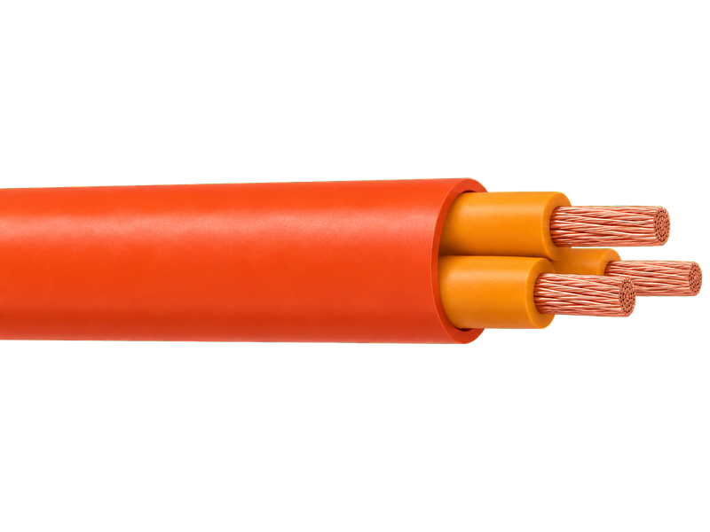
This power cable is designed for fixed low-voltage power transmission and distribution systems with a rated voltage of 0.6/1 kV. Manufactured in full compliance with IEC 60502-1, it delivers safe, efficient and long-lasting performance across industrial, commercial and residential electrical installations.
Key Advantages
-
Flame Retardant
-
Steel Wire Armour
-
UV Resistant
-
Full IEC 60502-1 Compliance
Construction
Conductors
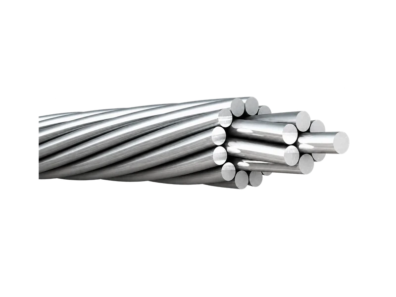
The conductors shall be either of Class 1 or Class 2 of plain or metal-coated annealed copper or of plain aluminium or aluminium alloy, or ofClass 5 of plain or metal-coated copper in accordance with IEC 60228.
Insulation
PVC Insulation material and thickness shall be as per IEC 60502-1, PVC material shall be Type A as per IEC 60502-1.
Assembly / Inner Covering
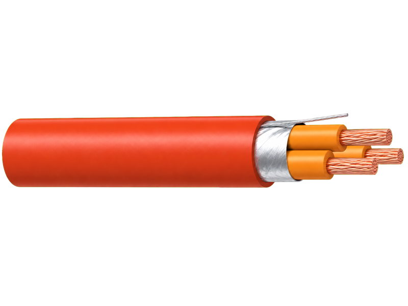
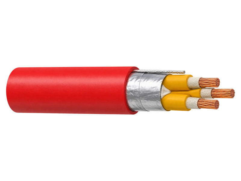
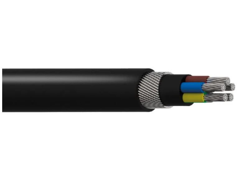
The inner coverings may be extruded or lapped. For cables with circular cores, except cables with more than five cores, a lapped inner coveringshall be permitted only if the interstices between the cores are substantially filled. A suitable binder is permitted before application of an extrudedinner covering. The materials used for inner coverings and fillers shall be suitable for the operating temperature of the cable and compatible withthe insulating material.For halogen free cables, the inner covering and fillers shall also be halogen free compound.
Armour
Aluminum/galvanized steel/steel wires applied helically over the Inner Covering as per IEC 60502-1, or double aluminum/steel tapes andcopper/tinned copper wire can also be manufactured upon request.
Outer Sheath
Outer sheath shall be of extruded PVC Type ST1/ST2 as per IEC 60502-1, Polyethylene type ST3/ST7, Halogen free compound ST8,Polychloroprene, chlorosulfonated polyethylene or similar polymers, type SE1 are also available on request.
Fire Performance of Cable Sheaths
Cables can be supplied with special flame retardant PVC outer sheath to comply with the flame test requirements of IEC 60332-3-22, IEC
60332-3-23 and IEC 60332-3-24, Halogen Free material comply to IEC60754-1/2 and IEC 60684-2.
Colour Code(1)
1 Core : Red or Black
2 Cores: Red, Black
3 Cores: Red, Yellow, Blue
4 Cores: Red, Yellow, Blue, Black
5 Cores: Red, Yellow, Blue, Black, Green
Above 5 Cores: Black Cores with White numerals
Color Code (2)
1 Core : Brown or Blue
2 Cores : Brown, Blue
3 Cores : Brown, Black, Grey
4 Cores : Blue, Brown, Black, Grey
5 Cores : Green/Yellow, Blue, Brown, Black, Grey
Above 5 Cores: Black Cores with White numerals
Other colors can be manufactured upon request.
Parameters
IEC 60502-1
Select a standard below to view the corresponding technical data. Our conductors are manufactured and tested in full compliance with international specifications.
| Nominal Cross Section | Diameter of Conductor (Approx.) | Nominal Insulation Thickness | Nominal Sheath Thickness | Overall Diameter (Approx.) |
|---|---|---|---|---|
| mm^2 | mm | mm | mm | mm |
| 1x4 | 2.3 | 1 | 1.4 | 7.1 |
| 1x6 | 2.8 | 1 | 1.4 | 7.6 |
| 1x10 | 3.6 | 1 | 1.4 | 8.4 |
| 1x16 | 4.5 | 1 | 1.4 | 9.3 |
| 1x25 | 5.6 | 1.2 | 1.4 | 10.8 |
| 1x35 | 6.7 | 1.2 | 1.4 | 11.9 |
| 1x50 | 8 | 1.4 | 1.4 | 13.6 |
| 1x70 | 9.4 | 1.4 | 1.4 | 15.1 |
| 1x95 | 11 | 1.6 | 1.5 | 17.2 |
| 1x120 | 12.4 | 1.6 | 1.5 | 18.7 |
| 1x150 | 13.8 | 1.8 | 1.6 | 20.6 |
| 1x185 | 15.3 | 2 | 1.7 | 22.7 |
| 1x240 | 17.5 | 2.2 | 1.8 | 25.4 |
| 1x300 | 19.5 | 2.4 | 1.9 | 28.0 |
| 1x400 | 22.6 | 2.6 | 2.0 | 31.7 |
| 1x500 | 25.2 | 2.8 | 2.1 | 35.0 |
| 1x630 | 28.3 | 2.8 | 2.2 | 38.3 |
| Nominal Cross Section | Diameter of Conductor (Approx.) | Nominal Insulation Thickness | Nominal Sheath Thickness | Overall Diameter (Approx.) |
|---|---|---|---|---|
| mm² | mm | mm | mm | mm |
| 2x2.5 | 1.8 | 0.8 | 1.8 | 10.4 |
| 2x4 | 2.3 | 1 | 1.8 | 12.2 |
| 2x6 | 2.8 | 1 | 1.8 | 13.2 |
| 2x10 | 3.6 | 1 | 1.8 | 14.8 |
| 2x16 | 4.5 | 1 | 1.8 | 16.6 |
| 2x25 | 5.6 | 1.2 | 1.8 | 19.6 |
| 2x35 | 6.7 | 1.2 | 1.8 | 21.8 |
| 2x50 | 8 | 1.4 | 1.8 | 25.2 |
| 2x70 | 9.4 | 1.4 | 1.9 | 28.1 |
| 2x95 | 11 | 1.6 | 2.0 | 32.4 |
| 2x120 | 12.4 | 1.6 | 2.1 | 35.4 |
| 2x150 | 13.8 | 1.8 | 2.2 | 39.2 |
| 2x185 | 15.3 | 2 | 2.4 | 43.3 |
| 2x240 | 17.5 | 2.2 | 2.5 | 48.9 |
| 2x300 | 19.5 | 2.4 | 2.7 | 54.0 |
| 2x400 | 22.6 | 2.6 | 2.9 | 61.5 |
| Nominal Cross Section | Diameter of Conductor (Approx.) | Nominal Insulation Thickness | Nominal Sheath Thickness | Overall Diameter (Approx.) |
|---|---|---|---|---|
| mm² | mm | mm | mm | mm |
| 3x2.5 | 1.8 | 0.8 | 1.8 | 10.9 |
| 3x4 | 2.3 | 1 | 1.8 | 12.9 |
| 3x6 | 2.8 | 1 | 1.8 | 13.9 |
| 3x10 | 3.6 | 1 | 1.8 | 15.7 |
| 3x16 | 4.5 | 1 | 1.8 | 17.6 |
| 3x25 | 5.6 | 1.2 | 1.8 | 20.8 |
| 3x35 | 6.7 | 1.2 | 1.8 | 23.2 |
| 3x50 | 8 | 1.4 | 1.8 | 26.9 |
| 3x70 | 9.4 | 1.4 | 1.9 | 30.1 |
| 3x95 | 11 | 1.6 | 2.1 | 34.7 |
| 3x120 | 12.4 | 1.6 | 2.2 | 38.0 |
| 3x150 | 13.8 | 1.8 | 2.3 | 42.1 |
| 3x185 | 15.3 | 2 | 2.5 | 46.5 |
| 3x240 | 17.5 | 2.2 | 2.7 | 52.5 |
| 3x300 | 19.5 | 2.4 | 2.8 | 58.0 |
| 3x400 | 22.6 | 2.6 | 3.1 | 66.1 |
| Nominal Cross Section | Diameter of Conductor (Approx.) | Nominal Insulation Thickness | Nominal Sheath Thickness | Overall Diameter (Approx.) |
|---|---|---|---|---|
| mm² | mm | mm | mm | mm |
| 3x16/10 | 4.5 | 3.6 | 1 | 1 |
| 3x25/16 | 5.6 | 4.5 | 1.2 | 1 |
| 3x35/16 | 6.7 | 4.5 | 1.2 | 1 |
| 3x50/25 | 8.0 | 5.6 | 1.4 | 1.2 |
| 3x70/35 | 9.4 | 6.7 | 1.4 | 1.2 |
| 3x95/50 | 11.0 | 8.0 | 1.6 | 1.4 |
| 3x120/70 | 12.4 | 9.4 | 1.6 | 1.4 |
| 3x150/70 | 13.8 | 9.4 | 1.8 | 1.4 |
| 3x185/95 | 15.3 | 11.0 | 2 | 1.6 |
| 3x240/120 | 17.5 | 12.4 | 2.2 | 1.6 |
| 3x300/150 | 19.5 | 13.8 | 2.4 | 1.8 |
| 3x400/185 | 22.6 | 15.3 | 2.6 | 2 |
| Nominal Cross Section | Diameter of Conductor (Approx.) | Nominal Insulation Thickness | Nominal Sheath Thickness | Overall Diameter (Approx.) |
|---|---|---|---|---|
| mm² | mm | mm | mm | mm |
| 4x2.5 | 1.8 | 0.8 | 1.8 | 11.8 |
| 4x4 | 2.3 | 1 | 1.8 | 14.0 |
| 4x6 | 2.8 | 1 | 1.8 | 15.2 |
| 4x10 | 3.6 | 1 | 1.8 | 17.1 |
| 4x16 | 4.5 | 1 | 1.8 | 19.3 |
| 4x25 | 5.6 | 1.2 | 1.8 | 22.9 |
| 4x35 | 6.7 | 1.2 | 1.8 | 25.6 |
| 4x50 | 8 | 1.4 | 1.9 | 29.9 |
| 4x70 | 9.4 | 1.4 | 2.0 | 33.5 |
| 4x95 | 11 | 1.6 | 2.2 | 38.7 |
| 4x120 | 12.4 | 1.6 | 2.3 | 42.3 |
| 4x150 | 13.8 | 1.8 | 2.5 | 46.9 |
| 4x185 | 15.3 | 2 | 2.6 | 51.9 |
| 4x240 | 17.5 | 2.2 | 2.9 | 58.6 |
| 4x300 | 19.5 | 2.4 | 3.1 | 64.8 |
| 4x400 | 22.6 | 2.6 | 3.3 | 73.8 |
| Nominal Cross Section | Diameter of Conductor (Approx.) | Nominal Insulation Thickness | Nominal Sheath Thickness | Overall Diameter (Approx.) |
|---|---|---|---|---|
| mm² | mm | mm | mm | mm |
| 7x1.5 | 1.4 | 0.8 | 1.8 | 12.6 |
| 10x1.5 | 1.4 | 0.8 | 1.8 | 15.6 |
| 12x1.5 | 1.4 | 0.8 | 1.8 | 16.1 |
| 14x1.5 | 1.4 | 0.8 | 1.8 | 16.8 |
| 19x1.5 | 1.4 | 0.8 | 1.8 | 18.6 |
| 21x1.5 | 1.4 | 0.8 | 1.8 | 19.5 |
| 24x1.5 | 1.4 | 0.8 | 1.8 | 21.6 |
| 30x1.5 | 1.4 | 0.8 | 1.8 | 22.8 |
| 40x1.5 | 1.4 | 0.8 | 1.8 | 27.7 |
| 48x1.5 | 1.4 | 0.8 | 1.9 | 28.2 |
| 61x1.5 | 1.4 | 0.8 | 1.9 | 30.9 |
| 5x2.5 | 1.8 | 0.8 | 1.8 | 12.8 |
| 7x2.5 | 1.8 | 0.8 | 1.8 | 13.8 |
| 10x2.5 | 1.8 | 0.8 | 1.8 | 17.2 |
| 12x2.5 | 1.8 | 0.8 | 1.8 | 17.7 |
| 14x2.5 | 1.8 | 0.8 | 1.8 | 18.6 |
| 19x2.5 | 1.8 | 0.8 | 1.8 | 20.6 |
| 21x2.5 | 1.8 | 0.8 | 1.8 | 21.6 |
| 24x2.5 | 1.8 | 0.8 | 1.8 | 24.0 |
| 30x2.5 | 1.8 | 0.8 | 1.8 | 25.4 |
| 40x2.5 | 1.8 | 0.8 | 2.0 | 31.1 |
| 48x2.5 | 1.8 | 0.8 | 2.0 | 31.7 |
| 61x2.5 | 1.8 | 0.8 | 2.1 | 34.7 |
| Nominal Cross Section | Diameter of Conductor (Approx.) | Nominal Insulation Thickness | Nominal Sheath Thickness | Overall Diameter (Approx.) |
|---|---|---|---|---|
| mm² | mm | mm | mm | mm |
| 3x2.5 | 1.8 | 0.8 | 1.8 | 10.9 |
| 3x4 | 2.3 | 1 | 1.8 | 12.9 |
| 3x6 | 2.8 | 1 | 1.8 | 13.9 |
| 3x10 | 3.6 | 1 | 1.8 | 15.7 |
| 3x16 | 4.5 | 1 | 1.8 | 17.6 |
| 3x25 | 5.6 | 1.2 | 1.8 | 20.8 |
| 3x35 | 6.7 | 1.2 | 1.8 | 23.2 |
| 3x50 | 8 | 1.4 | 1.8 | 26.9 |
| 3x70 | 9.4 | 1.4 | 1.9 | 30.1 |
| 3x95 | 11 | 1.6 | 2.1 | 34.7 |
| 3x120 | 12.4 | 1.6 | 2.2 | 38.0 |
| 3x150 | 13.8 | 1.8 | 2.3 | 42.1 |
| 3x185 | 15.3 | 2 | 2.5 | 46.5 |
| 3x240 | 17.5 | 2.2 | 2.7 | 52.5 |
| 3x300 | 19.5 | 2.4 | 2.8 | 58.0 |
| 3x400 | 22.6 | 2.6 | 3.1 | 66.1 |
| Nominal Cross Section | Diameter of Conductor (Approx.) | Nominal Insulation Thickness | Nominal Inner Covering thickness | Nominal Steel Wiredia | Nominal Sheath thickness | Overall Diameter (Approx.) |
|---|---|---|---|---|---|---|
| mm^2 | mm | mm | mm | mm | mm | mm |
| 2x2.5 | 1.8 | 0.8 | 1.0 | 0.8 | 1.8 | 14.0 |
| 2x4 | 2.3 | 1 | 1.0 | 1.25 | 1.8 | 16.7 |
| 2x6 | 2.8 | 1 | 1.0 | 1.25 | 1.8 | 17.7 |
| 2x10 | 3.6 | 1 | 1.0 | 1.25 | 1.8 | 19.3 |
| 2x16 | 4.5 | 1 | 1.0 | 1.25 | 1.8 | 21.1 |
| 2x25 | 5.6 | 1.2 | 1.0 | 1.6 | 1.8 | 24.8 |
| 2x35 | 6.7 | 1.2 | 1.0 | 1.6 | 1.8 | 27.0 |
| 2x50 | 8 | 1.4 | 1.0 | 1.6 | 1.9 | 30.7 |
| 2x70 | 9.4 | 1.4 | 1.0 | 2.0 | 2.1 | 34.5 |
| 2x95 | 11 | 1.6 | 1.2 | 2.0 | 2.2 | 39.2 |
| 2x120 | 12.4 | 1.6 | 1.2 | 2.0 | 2.3 | 42.2 |
| 2x150 | 13.8 | 1.8 | 1.2 | 2.5 | 2.5 | 47.2 |
| 2x185 | 15.3 | 2 | 1.4 | 2.5 | 2.6 | 51.6 |
| 2x240 | 17.5 | 2.2 | 1.4 | 2.5 | 2.8 | 57.2 |
| 2x300 | 19.5 | 2.4 | 1.6 | 2.5 | 3.0 | 62.8 |
| 2x400 | 22.6 | 2.6 | 1.6 | 2.5 | 3.2 | 70.3 |
| Nominal Cross Section | Diameter of Conductor (Approx.) | Nominal Insulation Thickness | Nominal Inner Covering thickness | Nominal Steel Wiredia | Nominal Sheath thickness | Overall Diameter (Approx.) |
|---|---|---|---|---|---|---|
| mm^2 | mm | mm | mm | mm | mm | mm |
| 3x2.5 | 1.8 | 0.8 | 1.0 | 0.8 | 1.8 | 14.5 |
| 3x4 | 2.3 | 1 | 1.0 | 1.25 | 1.8 | 17.4 |
| 3x6 | 2.8 | 1 | 1.0 | 1.25 | 1.8 | 18.4 |
| 3x10 | 3.6 | 1 | 1.0 | 1.25 | 1.8 | 20.2 |
| 3x16 | 4.5 | 1 | 1.0 | 1.6 | 1.8 | 22.8 |
| 3x25 | 5.6 | 1.2 | 1.0 | 1.6 | 1.8 | 26.0 |
| 3x35 | 6.7 | 1.2 | 1.0 | 1.6 | 1.9 | 28.5 |
| 3x50 | 8.0 | 1.4 | 1.0 | 2 | 2.0 | 33.3 |
| 3x70 | 9.4 | 1.4 | 1.2 | 2 | 2.1 | 37.0 |
| 3x95 | 11.0 | 1.6 | 1.2 | 2 | 2.3 | 41.6 |
| 3x120 | 12.4 | 1.6 | 1.2 | 2.5 | 2.4 | 45.9 |
| 3x150 | 13.8 | 1.8 | 1.4 | 2.5 | 2.6 | 50.4 |
| 3x185 | 15.3 | 2 | 1.4 | 2.5 | 2.7 | 54.8 |
| 3x240 | 17.5 | 2.2 | 1.5 | 2.5 | 2.9 | 61.2 |
| 3x300 | 19.5 | 2.4 | 1.6 | 2.5 | 3.1 | 66.8 |
| 3x400 | 22.6 | 2.8 | 1.6 | 3.15 | 3.4 | 76.7 |
| 3x500 | 25.2 | 2.8 | 1.8 | 3.15 | 3.7 | 83.6 |
| Nominal Cross Section |
Diameter of Conductor (Approx.) |
Nominal Insulation thickness |
Nominal Inner Covering thickness |
Nominal Steel Wire dia. |
Nominal Sheath thickness |
Overall Diameter (Approx.) |
||
|---|---|---|---|---|---|---|---|---|
| mm^2 | mm | mm | mm | mm | mm | mm | mm | mm |
| 3x10/6 | 3.6 | 2.8 | 1 | 1 | 1 | 1.25 | 1.8 | 21.9 |
| 3x16/10 | 4.5 | 3.6 | 1 | 1 | 1 | 1.6 | 1.8 | 24.2 |
| 3x25/16 | 5.6 | 4.5 | 1.2 | 1 | 1 | 1.6 | 1.8 | 27.9 |
| 3x35/16 | 6.7 | 4.5 | 1.2 | 1 | 1 | 1.6 | 1.9 | 30.8 |
| 3x50/25 | 8.0 | 5.6 | 1.4 | 1.2 | 1 | 2.0 | 2.0 | 36.4 |
| 3x70/35 | 9.4 | 6.7 | 1.4 | 1.2 | 1.2 | 2.0 | 2.1 | 40.1 |
| 3x95/50 | 11.0 | 8.0 | 1.6 | 1.4 | 1.2 | 2.5 | 2.3 | 46.3 |
| 3x120/70 | 12.4 | 9.4 | 1.6 | 1.4 | 1.4 | 2.5 | 2.4 | 50.3 |
| 3x150/70 | 13.8 | 9.4 | 1.8 | 1.4 | 1.4 | 2.5 | 2.6 | 55.0 |
| 3x185/95 | 15.3 | 11.0 | 2 | 1.6 | 1.4 | 2.5 | 2.7 | 60.3 |
| 3x240/120 | 17.5 | 12.4 | 2.2 | 1.6 | 1.6 | 2.5 | 2.9 | 67.0 |
| 3x300/150 | 19.5 | 13.8 | 2.4 | 1.8 | 1.6 | 3.15 | 3.1 | 74.6 |
| 3x400/185 | 22.6 | 15.3 | 2.6 | 2 | 1.8 | 3.15 | 3.4 | 84.1 |
| 3x500/240 | 25.2 | 17.5 | 2.8 | 2.2 | 2 | 3.15 | 3.7 | 91.8 |
| Nominal Cross Section | Diameter of Conductor (Approx.) | Nominal Insulation Thickness | Nominal Inner Covering thickness | Nominal Steel Wiredia | Nominal Sheath thickness | Overall Diameter (Approx.) |
|---|---|---|---|---|---|---|
| mm^2 | mm | mm | mm | mm | mm | mm |
| 4x4 | 2.3 | 1 | 1 | 1.25 | 1.8 | 18.5 |
| 4x6 | 2.8 | 1 | 1 | 1.25 | 1.8 | 19.7 |
| 4x10 | 3.6 | 1 | 1 | 1.25 | 1.8 | 22.3 |
| 4x16 | 4.5 | 1 | 1 | 1.6 | 1.8 | 24.5 |
| 4x25 | 5.6 | 1.2 | 1 | 1.6 | 1.9 | 28.2 |
| 4x35 | 6.7 | 1.2 | 1 | 1.6 | 2.0 | 31.1 |
| 4x50 | 8.0 | 1.4 | 1 | 2.0 | 2.1 | 36.7 |
| 4x70 | 9.4 | 1.4 | 1.2 | 2.0 | 2.3 | 40.4 |
| 4x95 | 11.0 | 1.6 | 1.2 | 2.5 | 2.5 | 46.6 |
| 4x120 | 12.4 | 1.6 | 1.4 | 2.5 | 2.6 | 50.6 |
| 4x150 | 13.8 | 1.8 | 1.4 | 2.5 | 2.7 | 55.3 |
| 4x185 | 15.3 | 2 | 1.4 | 2.5 | 2.9 | 60.6 |
| 4x240 | 17.5 | 2.2 | 1.6 | 2.5 | 3.1 | 67.3 |
| 4x300 | 19.5 | 2.4 | 1.6 | 3.15 | 3.4 | 74.9 |
| 4x400 | 22.6 | 2.6 | 1.8 | 3.15 | 3.7 | 84.4 |
| 4x500 | 25.2 | 2.8 | 2 | 3.15 | 3.9 | 92.1 |
Request the Complete Data Sheet
Application

Commercial Buildings
Mains power supply for high-rise buildings, shopping centers, hotels, hospitals, and office complexes.

Power Networks
Underground power distribution networks in urban areas, utility substations, and grid infrastructure projects.

Petrochemical
Oil refineries, chemical plants, and petrochemical facilities with robust mechanical and environmental protection.

Renewable Energy
Solar power plants, wind farms, and renewable energy projects requiring durable outdoor-rated cables.
faq
What is the difference between IEC 60502-1 and BS 5467 cables?
IEC 60502-1 is the international standard for low voltage PVC insulated power cables up to 1kV, while BS 5467 is the British standard for armoured cables. Both standards cover similar cable types for 0.6/1kV applications. Our cables are manufactured to meet IEC 60502-1 requirements and can also be supplied to comply with BS 5467 upon request. The key differences are in dimensional tolerances and specific marking requirements, but the electrical and mechanical performance are essentially equivalent for most installation purposes.
Should I choose copper or aluminum conductor?
The choice depends on your project requirements:
- Copper conductors offer higher conductivity, better mechanical strength, smaller diameter for equivalent current rating, superior corrosion resistance, and easier termination. Recommended for industrial applications, smaller cross-sections, and where reliability is critical.
- Aluminum conductors provide significant cost savings (typically 30-40% material cost reduction), lighter weight for easier installation, and are commonly used for larger cross-sections in utility distribution and construction projects. Note that aluminum requires larger conductor sizes for equivalent ampacity and proper anti-oxidant treatment at terminations.
When do I need armoured cable?
Steel wire armour (SWA) or steel tape armour (STA) is recommended in the following scenarios:
- Direct burial in the ground without conduit protection
- Areas with risk of mechanical damage (construction sites, heavy traffic areas)
- Underground duct banks where pulling forces may be high
- Outdoor installations exposed to potential impact or rodent damage
- Industrial environments with heavy machinery and equipment
Unarmoured cables are suitable for indoor installation in cable trays, conduits, wall chases, and other protected locations where mechanical damage risk is minimal.
What is the recommended burial depth for direct buried armoured cable?
Standard burial depth recommendations for SWA armoured cables:
- General areas (footpaths, grass verges): minimum 600mm (24 inches) below ground level
- Under roads and driveways: minimum 900mm (36 inches) below ground level
- Under agricultural land: minimum 1000mm (40 inches)
Cables should be laid on a bed of clean sand or sifted soil, covered with sand, then protected with cable protection tiles or warning tape before backfilling. Always verify local electrical codes and regulations as requirements may vary by region.
Can you manufacture custom cable specifications?
Yes, we offer extensive customization options to meet specific project requirements including:
- Special core configurations (e.g., 3+1E, 3+2E, 4+1E, custom multi-core)
- Custom outer sheath colors (red, blue, grey, etc. for identification)
- Special print marking with customer logo, project name, or custom text
- Low smoke zero halogen (LSZH) versions for special fire safety requirements
- UV-stabilized formulations for extreme outdoor exposure
- Oil-resistant and chemical-resistant sheath compounds
- Custom length drums and packaging
Custom orders typically require MOQ and may have slightly longer lead times. Contact our sales team with your specific requirements for a quote.
What is the typical lead time for orders?
Typical production lead times:
- Standard specifications (common sizes): 7-15 working days after order confirmation
- Custom specifications or special requirements: 15-25 working days
- Large volume orders: production schedule confirmed at time of order
We also maintain inventory of fast-moving standard sizes for immediate shipment. Transit time depends on destination port and shipping method. We can ship by sea (most cost-effective for large orders), air (urgent shipments), or rail (for Central Asian destinations).
Request for Free Consultation
Contact Information
Send us your cable requirements and our team will respond quickly with product recommendations, technical support and quotation details.