SAC Covered Conductor for Spaced Aerial Systems
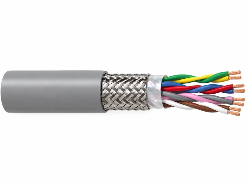
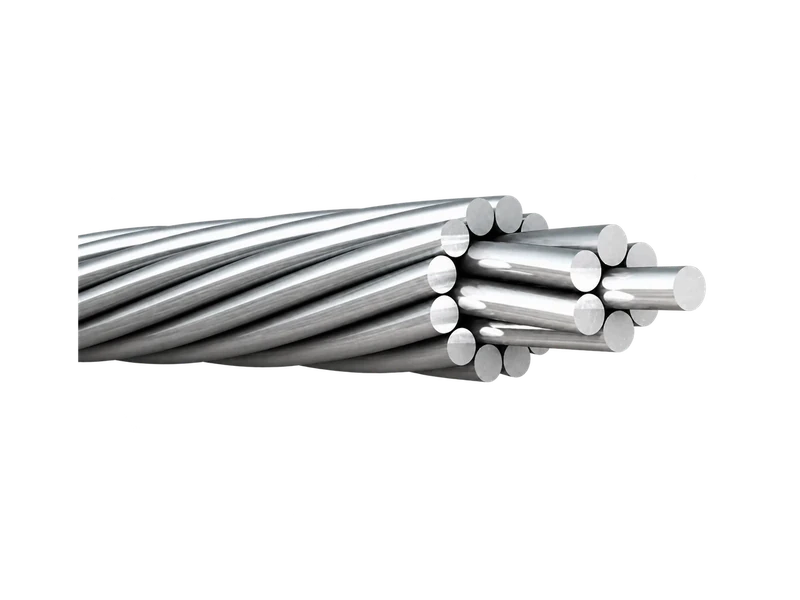
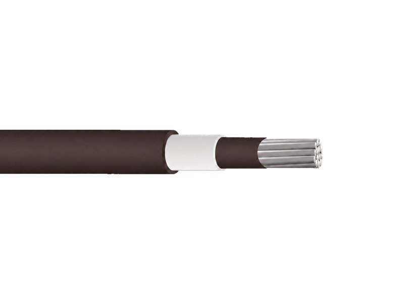
SAC aluminium spaced aerial cable is a covered single-core phase conductor for medium-voltage overhead systems. Available designs correspond to maximum system voltages of 15 kV, 25 kV and 35 kV, with 10 kV, 20 kV and 33 kV phase-to-phase ratings in the available product range. The conductor uses compact hard-drawn aluminium, a semiconductive conductor screen, XLPE insulation and a black track-resistant outer layer for spaced-aerial line arrangements.
Product Overview
SAC is the covered phase conductor within a spaced-aerial system. The compact aluminium conductor controls the metallic diameter, the semiconductive screen forms the conductor interface, XLPE provides the principal insulation, and the track-resistant outer layer addresses surface electrical stress and outdoor exposure. Layer thickness and finished diameter change with the voltage class and conductor size.
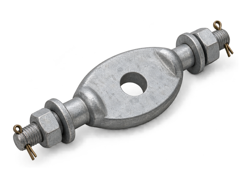
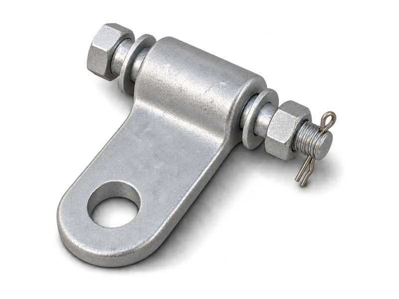
A complete SAC installation also requires a messenger, spacers, clamps, connectors and a defined line geometry; these components are not automatically included with the phase conductor. Product selection should follow the applicable ICEA, TIS, MEA, PEA, PDITL or project requirement and should identify maximum system voltage, phase-to-phase voltage, conductor size, route environment, phase spacing, support duty and required tests.
Key Features
- Compacted aluminium phase conductor:A compact hard-drawn aluminium conductor provides the phase core and controls overall conductor diameter, supporting the close, regular spacing required by the SAC overhead arrangement.
- Semiconductive conductor screen:The semiconductive conductor screen creates a controlled electrical interface beneath the XLPE insulation, forming the defined layer sequence required for the listed medium-voltage construction.
- Track-resistant outer layer:A black track-resistant outer layer protects the insulation surface against the electrical stress and environmental exposure associated with an outdoor spaced-aerial system.
- Voltage-specific construction tables:Separate 15 kV, 25 kV and 35 kV tables keep layer thickness and finished dimensions tied to voltage, enabling more accurate selection of spacers, clamps, connectors and reels.
Product Applications
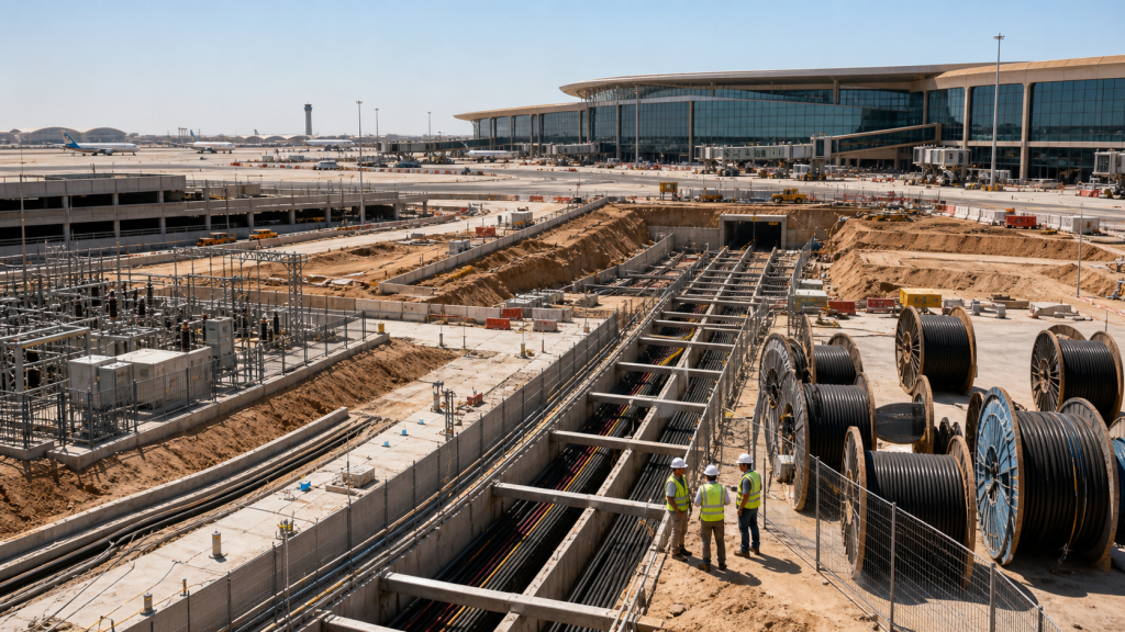
- Primary overhead distribution on poles or steel structures using a complete SAC system specified by the utility
- Restricted urban or industrial corridors where controlled conductor spacing provides a compact three-phase overhead route
- Projects governed by MEA, PEA, PDITL or the cited Thai standard schedules, with voltage-specific conductors and hardware
Technical Specifications
Technical data below covers Thai utility SAC constructions for 15 kV, 25 kV and 35 kV systems. The 25 kV and 35 kV designs follow TIS 2341-2555 with applicable MEA/PEA requirements, while the 15 kV design follows the applicable MEA/PEA utility specification with ICEA S-66-524 reference.
15 kV SAC
| Nominal cross–sectional area / mm² | Minimum number of wire No. | Diameter of conductor (Approx.) /mm | Thickness of insulation / mm | Thickness of sheath / mm | Overall diameter (Approx.) / mm | Maximum DC. conductor resistance at 20°C Ω/km | Minimum insulation resistance at 15.6°C M Ω-km | Allowable amp acitiesin free air at40°C ambient A | Cable weight (Approx.) kg/km |
|---|---|---|---|---|---|---|---|---|---|
| 35 | 6 | 6.9 | 1.91 | 1.91 | 16 | 0.868 | 1820 | 151 | 232 |
| 50 | 6 | 8 | 1.91 | 1.91 | 17.5 | 0.641 | 1612 | 187 | 291 |
| 70 | 12 | 9.8 | 1.91 | 1.91 | 19 | 0.443 | 1445 | 231 | 358 |
| 95 | 15 | 11.4 | 1.91 | 1.91 | 21 | 0.32 | 1284 | 281 | 451 |
| 120 | 15 | 12.9 | 1.91 | 1.91 | 22.5 | 0.253 | 1152 | 324 | 552 |
| 150 | 15 | 14.1 | 1.91 | 1.91 | 24 | 0.206 | 1070 | 375 | 639 |
| 185 | 30 | 15.8 | 1.91 | 1.91 | 25.5 | 0.164 | 980 | 433 | 763 |
| 240 | 30 | 18.3 | 1.91 | 1.91 | 28 | 0.125 | 874 | 525 | 953 |
25 kV SAC
| Nominal cross–sectional area / mm² | Minimum number of wire No. | Diameter of conductor (Approx.) /mm | Thickness of insulation / mm | Thickness of sheath / mm | Overall diameter (Approx.) / mm | Maximum DC. conductor resistance at 20°C Ω/km | Minimum insulation resistance at 15.6°C M Ω-km | Allowable amp acitiesin free air at40°C ambient A | Cable weight (Approx.) kg/km |
|---|---|---|---|---|---|---|---|---|---|
| 35 | 6 | 6.9 | 3.18 | 3.18 | 21 | 0.868 | 2580 | 149 | 363 |
| 50 | 6 | 8 | 3.18 | 3.18 | 22 | 0.641 | 2314 | 186 | 432 |
| 70 | 12 | 9.8 | 3.18 | 3.18 | 24.5 | 0.443 | 2100 | 229 | 509 |
| 95 | 15 | 11.4 | 3.18 | 3.18 | 26 | 0.32 | 1887 | 279 | 615 |
| 120 | 15 | 12.9 | 3.18 | 3.18 | 27 | 0.253 | 1712 | 321 | 729 |
| 150 | 15 | 14.1 | 3.18 | 3.18 | 29.5 | 0.206 | 1600 | 371 | 826 |
| 185 | 30 | 15.8 | 3.18 | 3.18 | 31 | 0.164 | 1477 | 429 | 959 |
| 240 | 30 | 18.3 | 3.18 | 3.18 | 33.5 | 0.125 | 1328 | 520 | 1170 |
25 kV SAC
| Nominal cross–sectional area / mm² | Minimum number of wire No. | Diameter of conductor (Approx.) /mm | Thickness of insulation / mm | Thickness of sheath / mm | Overall diameter (Approx.) / mm | Maximum DC. conductor resistance at 20°C Ω/km | Minimum insulation resistance at 15.6°C M Ω-km | Allowable amp acitiesin free air at40°C ambient A | Cable weight (Approx.) kg/km |
|---|---|---|---|---|---|---|---|---|---|
| 50 | 6 | 8 | 4.45 | 3.18 | 25.5 | 0.641 | 2606 | 184 | 517 |
| 70 | 12 | 9.8 | 4.45 | 3.18 | 27.5 | 0.443 | 2375 | 227 | 599 |
| 95 | 15 | 11.4 | 4.45 | 3.18 | 29 | 0.32 | 2144 | 276 | 711 |
| 120 | 15 | 12.9 | 4.45 | 3.18 | 31 | 0.253 | 1952 | 318 | 831 |
| 150 | 15 | 14.1 | 4.45 | 3.18 | 32.5 | 0.206 | 1830 | 367 | 933 |
| 185 | 30 | 15.8 | 4.45 | 3.18 | 33.5 | 0.164 | 1694 | 425 | 1073 |
| 240 | 30 | 18.3 | 4.45 | 3.18 | 36.5 | 0.125 | 1529 | 515 | 1293 |
Request the Complete Data Sheet
From Production to Delivery
From raw material preparation to final shipmen, every stage is caretuly controled to ensure consistent conductor quality, reliable pertormance,and sae delivery. Our roduction,
inspection, packaging, and logistics processes are managed in accordance with applicable standards and project requirements.
Production
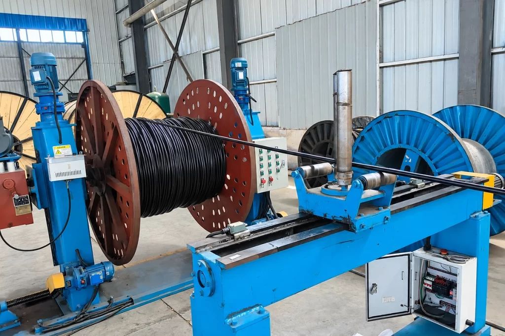
Hard-drawn aluminium wires are compacted into the scheduled conductor, then the semiconductive screen, XLPE insulation and black track-resistant outer layer are applied in the specified sequence.
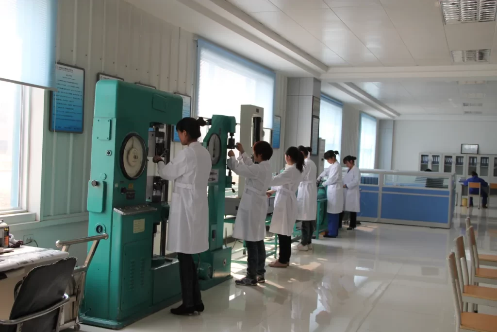
Inspection
Inspection checks conductor compaction and resistance, screen and insulation thicknesses, outer-layer surface, overall dimensions and the electrical or mechanical tests required by the relevant utility schedule.
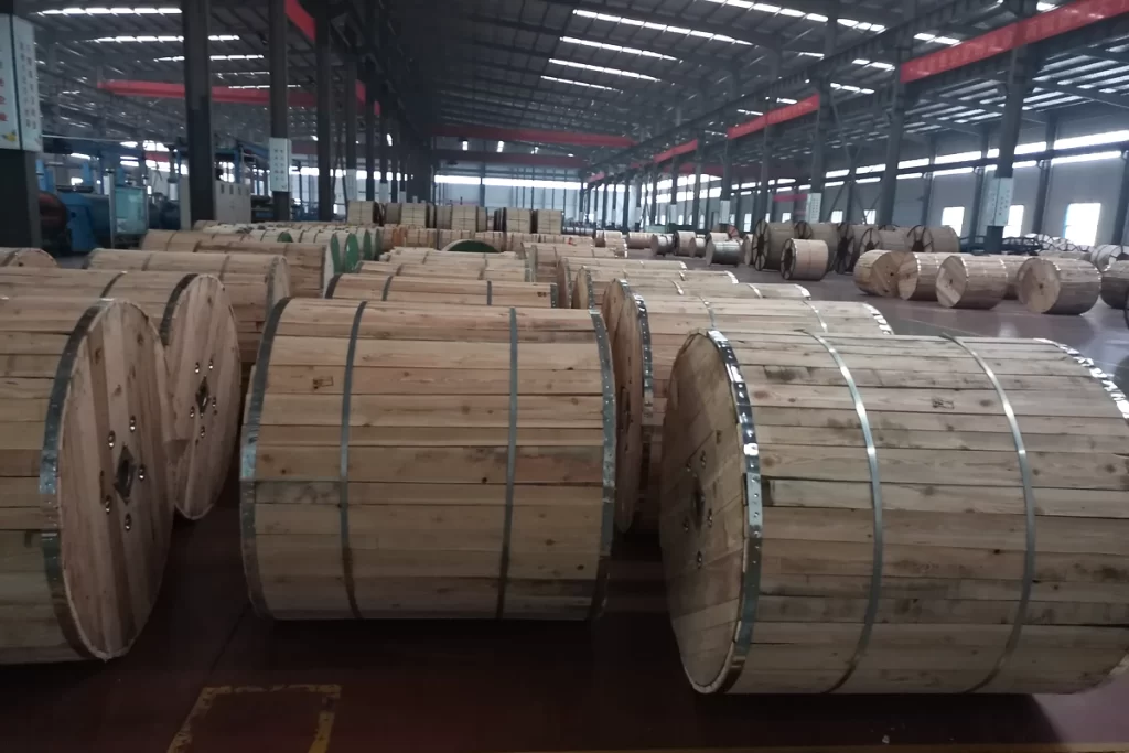
Packaging
Reel diameter, lagging and end protection are selected to preserve the track-resistant surface and bend limits, while project delivery lengths are planned around the intended overhead installation sections.
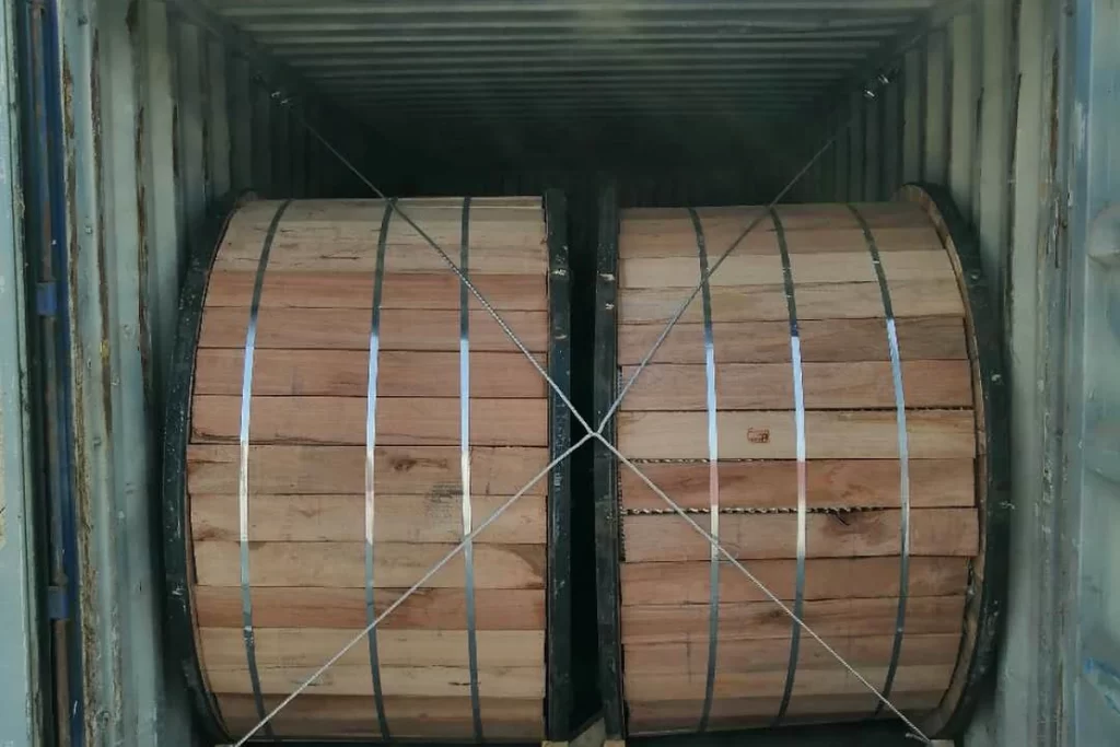
Shipping
Drum labels state SAC voltage class, conductor size, controlling specification, length and production lot, allowing phase conductors for different voltage groups to remain clearly separated during receiving and erection.
Frequently Asked Questions
Does an SAC quotation cover only the phase conductor?
The SAC product is the covered phase conductor. A complete spaced-aerial system also requires a messenger, spacers, clamps, connectors and defined line geometry. Tell us whether you need the conductor only or a coordinated hardware package, and we will itemise the required components.
How do I select the correct SAC voltage construction?
State both the maximum system voltage and the phase-to-phase operating voltage used by the project. The available range links 15/25/35 kV maximum system voltages with 10/20/33 kV phase-to-phase ratings. We will identify the corresponding layer thickness and finished dimensions in the quotation.
Why are both XLPE insulation and a track-resistant layer used?
XLPE provides the listed dielectric layer, while the black outer material addresses surface tracking and outdoor exposure. We will describe both layers separately in the quotation, making it clear that the outer layer has a different role from the insulation beneath it.
Can ordinary cable clamps be used on SAC?
SAC hardware should suit the finished diameter, surface and mechanical arrangement of the spaced-aerial system. If you send the conductor size, voltage and support geometry, we can include relevant clamp and spacer options for your engineer to assess against the utility’s required tests.
Can SAC be supplied for direct burial or duct installation?
SAC is designed for a supported overhead system, not for direct burial or installation in ducts. For an underground route, send us the voltage and installation conditions and we will propose a screened, sheathed power-cable construction suited to that environment.
What information helps you prepare an SAC offer?
Please send voltage class, utility or standard reference, conductor size, phase spacing, messenger and spacer requirements, route environment, quantity, reel lengths, fittings and inspection documents. A line drawing helps us present the conductor and related system items in a clearer commercial schedule.
Request for Free Consultation
Contact Information
Send us your cable requirements and our team will respond quickly with product recommendations, technical support and quotation details.