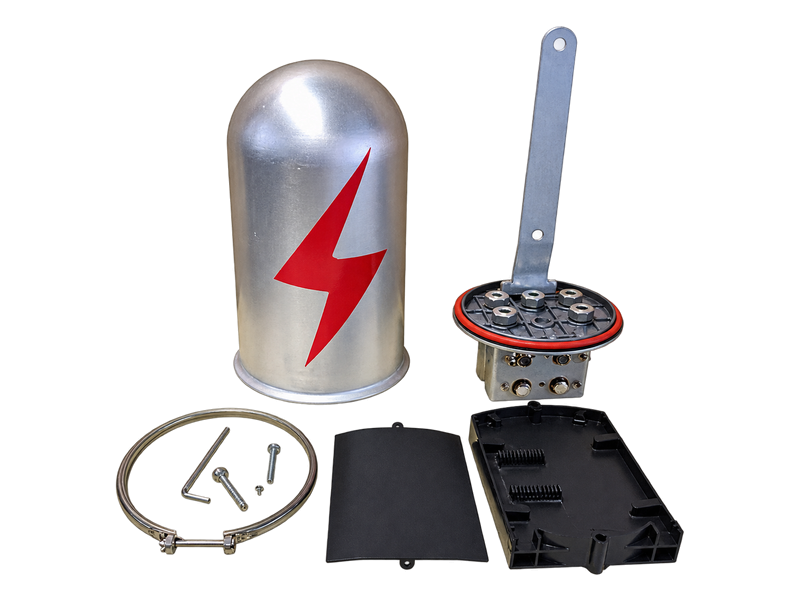
OPGW Metal Splice Closure for Towers and Poles
The OPGW Metal Splice Closure for Towers and Poles, also known as an OPGW joint box, OPGW splice box or OPGW joint closure, protects fusion splices and organised fibre reserves at a joint location. The Splice Closure uses an aluminium-alloy housing and is available in tower- and pole-mounting models with two or three cable ports and listed capacities from 12 to 60 fibres. Selection considers port layout, fibre count, cable entry, mounting position and environmental requirements.
Product Overview
The Splice Closure provides a protected optical joint after OPGW has been mechanically terminated and routed down the structure. Inside the enclosure, splice trays organise fusion splices and fibre reserves for later access. At the exterior, cable-entry components and mounting hardware connect the enclosure to the installed cable route. It is therefore part of the optical joint system, not a device for anchoring span tension and not a replacement for the Cable Storage Assembly.
Two-port and three-port versions serve different cable-entry layouts, while fibre capacity is selected separately from port count. Tower and pole models also use different mounting arrangements. Buyers should state the number and type of incoming cables, OPGW outside diameter and termination method, fibre and tube counts, splice plan, required ports, structure type, mounting height and any environmental or sealing requirement. The listed OPGW fibre optic splice closure range covers 12–60 fibres. A two-port or three-port OPGW joint box should therefore be selected from the actual joint arrangement rather than from fibre count alone, and a higher capacity requires a separately confirmed design.
Key Features
- Protected fibre management:The aluminium-alloy Splice Closure provides an enclosed location for fusion splices and organised fibre reserves at an OPGW joint point.
- Two- and three-port options:Different entry configurations allow the enclosure to follow the actual cable joint layout instead of forcing every splice point into one port pattern.
- 12–60-fibre listed range:Model tables separate fibre capacity from port count so selection can follow the planned splice allocation.
- Tower and pole mounting versions:Dedicated mounting arrangements coordinate enclosure position, cable routing and maintenance access on each structure type.
Product Applications
- Used at OPGW joint locations on transmission towers and poles for optical fibre splicing and cable connection management.
- Applied in utility transmission networks, grid expansion projects and OPGW maintenance works requiring protected fibre connection points.
- Suitable for new construction and replacement projects where OPGW splice points are required.
Technical Specifications
Metal Splice Closure For Tower
| Application | Specification Model | Suitable Range | Weight(kg) | Material |
|---|---|---|---|---|
| FOR TOWER | OGXT-2-012 | Two ports, 12 Fibers | 4.1 | Aluminium Alloy |
| OGXT-2-024 | Two ports, 24 Fibers | 4.1 | Aluminium Alloy | |
| OGXT-2-036 | Two ports, 36 Fibers | 4.1 | Aluminium Alloy | |
| OGXT-2-048 | Two ports, 48 Fibers | 4.1 | Aluminium Alloy | |
| OGXT-2-060 | Two ports, 60 Fibers | 4.1 | Aluminium Alloy | |
| OGXT-3-012 | Three ports, 12 Fibers | 4.2 | Aluminium Alloy | |
| OGXT-3-024 | Three ports, 24 Fibers | 4.2 | Aluminium Alloy | |
| OGXT-3-036 | Three ports, 36 Fibers | 4.2 | Aluminium Alloy | |
| OGXT-3-048 | Three ports, 48 Fibers | 4.2 | Aluminium Alloy | |
| OGXT-3-060 | Three ports, 60 Fibers | 4.2 | Aluminium Alloy |
Metal Splice Closure For Pole
| Application | Specification Model | Suitable Range | Weight(kg) | Material |
|---|---|---|---|---|
| FOR POLE | OGXG- 2-012 | Two ports, 12 Fibers | 4.1 | Aluminium Alloy |
| OGXG- 2-024 | Two ports, 24 Fibers | 4.1 | Aluminium Alloy | |
| OGXG- 2-036 | Two ports, 36 Fibers | 4.1 | Aluminium Alloy | |
| OGXG- 2-048 | Two ports, 48 Fibers | 4.1 | Aluminium Alloy | |
| OGXG- 2-060 | Two ports, 60 Fibers | 4.1 | Aluminium Alloy | |
| OGXG- 3-012 | Three ports, 12 Fibers | 4.2 | Aluminium Alloy | |
| OGXG- 3-024 | Three ports, 24 Fibers | 4.2 | Aluminium Alloy | |
| OGXG- 3-036 | Three ports, 36 Fibers | 4.2 | Aluminium Alloy | |
| OGXG- 3-048 | Three ports, 48 Fibers | 4.2 | Aluminium Alloy | |
| OGXG- 3-060 | Three ports, 60 Fibers | 4.2 | Aluminium Alloy |
Request the Complete Data Sheet
From Production to Delivery
From raw material preparation to final shipmen, every stage is caretuly controled to ensure consistent conductor quality, reliable pertormance,and sae delivery. Our roduction,
inspection, packaging, and logistics processes are managed in accordance with applicable standards and project requirements.
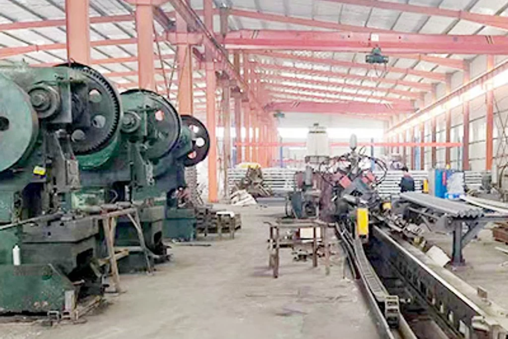
Production
The aluminium-alloy housing, cover, fibre-management parts, cable-entry components and mounting hardware are grouped as one Splice Closure kit. Port openings and internal organisers remain protected during handling.

Inspection
Inspection checks enclosure condition, cover and sealing interfaces, ports, internal trays or organisers, fasteners, mounting parts and model marking. Agreed ingress, optical or environmental verification is reviewed before release.
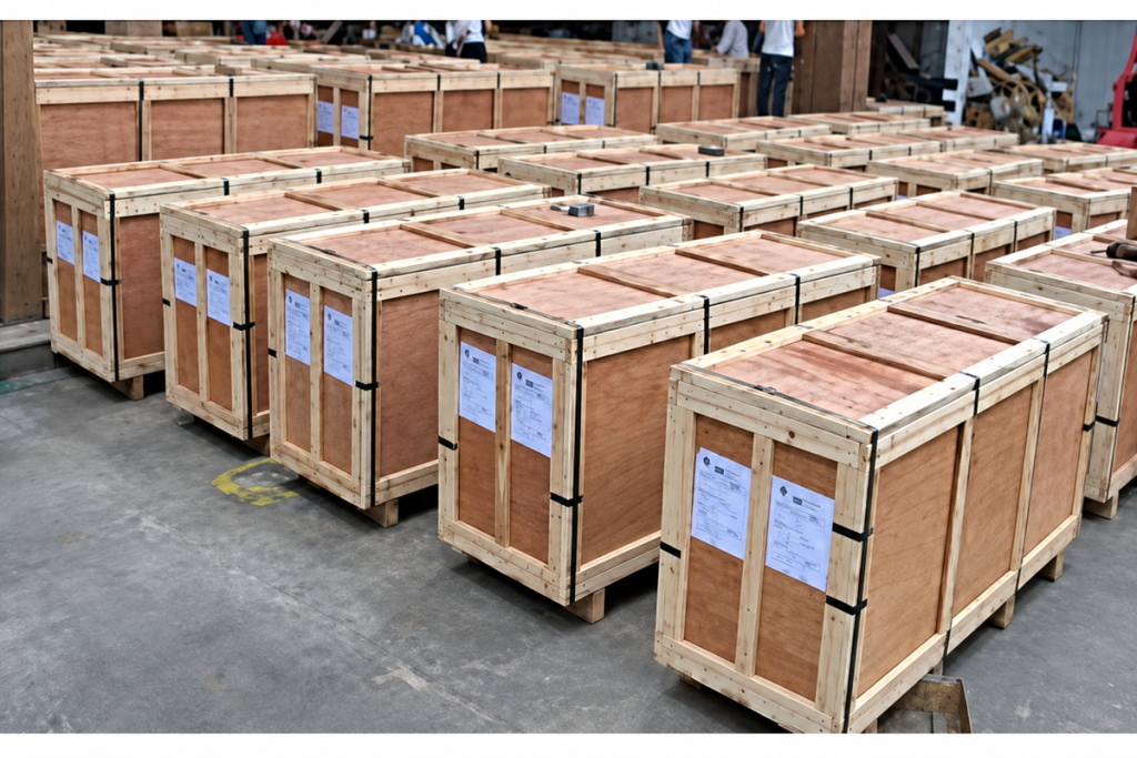
Packaging
Ports and internal parts are protected against contamination and impact, small accessories are bagged by closure, and the enclosure is cushioned against deformation. Package labels identify fibre capacity, port count and mounting version.

Shipping
Closures can be grouped with the corresponding Downlead Clamp and Cable Storage Assembly hardware for each joint location. Shipping documents may reference the splice point to preserve the planned cable-entry arrangement.
Frequently Asked Questions
Should I choose a two-port or three-port Splice Closure?
Choose from the approved cable-entry and splice plan. A straight joint may use two entries, while a branch or additional cable can require a third. Send the cable route and splice diagram; we will confirm the matching port arrangement and list the entry components.
What fibre capacities are available in this Splice Closure?
The listed tower and pole ranges provide 12, 24, 36, 48 and 60 fibres in both two-port and three-port versions. Tell us the fibre and tube counts plus the splice allocation, and we will select the correct capacity rather than relying only on the total fibre number.
Is the Splice Closure suitable for both towers and poles?
Yes, separate tower and pole model ranges are listed. The enclosure function is similar, but the supporting hardware and installation geometry differ. Please provide the structure drawing and proposed mounting height so the correct variant can be quoted.
Can the closure be reopened for maintenance or additional splicing?
The enclosure is designed for access to the protected splice area. Any re-entry should follow the approved instruction, including inspection or replacement of sealing components where required. We can confirm the supplied accessory and re-entry scope before order placement.
What cable-entry details do you need from us?
Please provide each cable type and outside diameter, OPGW termination arrangement, number of entries, fibre-tube construction, grounding or bonding detail, and the splice plan. We will use these inputs to define the port and internal-management configuration.
What installation conditions should be stated in the enquiry?
Identify the tower or pole, mounting height, ambient range, exposure, access method, downlead route and reserved cable length, together with the applicable utility specification. We will review the closure, mounting and related hardware as one maintainable joint location.
Request for Free Consultation
Contact Information
Send us your cable requirements and our team will respond quickly with product recommendations, technical support and quotation details.