Ball Eyes
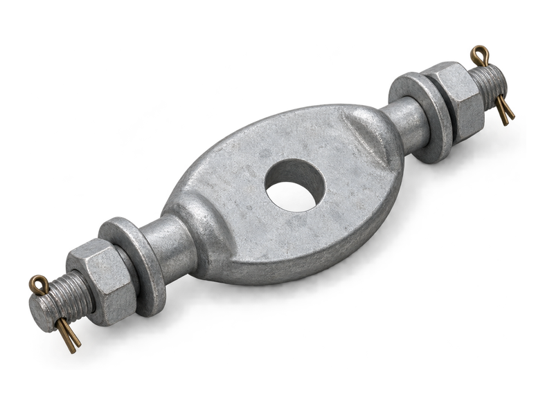
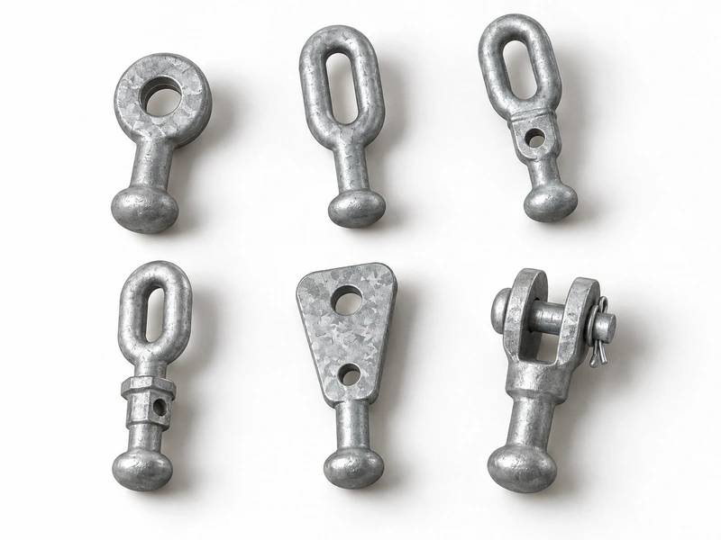
Ball eyes connect the socket end of an insulator to adjoining overhead line hardware through a single eye. The ball seats inside the insulator socket, while the eye receives the pin of a matching shackle or clevis. This arrangement carries mechanical load between the insulator and its attachment fittings in suspension and tension strings. Q and QP ball eyes differ in their eye geometry and connection dimensions, allowing the fitting to suit different assembly layouts. Ball eye fittings are selected by coupling size, eye dimensions and the mechanical requirements of the string.
Product Overview
The ball and eye perform different connection functions. Ball geometry determines the fit with the insulator socket; eye diameter and thickness determine the fit with the adjoining pin and clevis. The hot-dip galvanised steel body links these two interfaces.
Selection of ball eyes for insulator strings brings together coupling designation, mechanical rating and available assembly space. Eye shape and connection length affect clearance around adjacent fittings. Extended or differently oriented forms have their own dimensions within the product family.
Key Features
- Ball-to-eye connection: Combines a ball coupling and a single eye in one fitting.
- Pin-connected eye: The eye joins directly to a compatible shackle or clevis pin.
- Q and QP geometries: Different eye forms and dimensions accommodate different connection layouts.
- Galvanised steel body: A zinc coating protects the steel surface against atmospheric corrosion.
Product Applications
- Insulator strings: fitted between a socket-ended insulator and compatible link hardware in overhead line suspension and tension assemblies.
- Tower-side attachments: used with a mating shackle or clevis to connect the insulator string to its attachment hardware.
Technical Specifications
Ball Eyes (Type Q&QP)
| Catalog No. | Suitable Insulator | Dimensions(mm) | Raled Failure Load(kN) | Weight(kg) | |||||
|---|---|---|---|---|---|---|---|---|---|
| Di | D2 | d | b | h1 | h2 | ||||
| Q-7 | XP-7 | 33.3 | 17 | 22 | 16 | 50 | 13.4 | 70 | 0.3 |
| QP-7 | XP-7 | 33.3 | 17 | 20 | 16 | 50 | 13.4 | 70 | 0.3 |
| QP-10 | XP-10 | 33.3 | 17 | 20 | 16 | 50 | 13.4 | 100 | 0.3 |
| QP-16 | XP-16 | 41 | 21 | 26 | 20 | 60 | 19.5 | 160 | 0.5 |
| QP-20 | XP-20 | 49 | 25 | 30 | 24 | 80 | 21 | 200 | 1 |
| QP-21D | XP-21 | 41 | 21 | 29 | 24 | 70 | 19.5 | 210 | 1 |
| QP-30 | XP-30 | 49 | 25 | 39 | 30 | 80 | 21 | 300 | 1.1 |
Ball Eyes (Type QH)
| Catalog No. | SuitalbleInsulator | Dimensions(mm) | Rated Failure Load(kN) | Weight(kg) | |||||
|---|---|---|---|---|---|---|---|---|---|
| hi | h2 | h3 | R | D | b | ||||
| QH-7 | XP-7 | 13.4 | 114 | 57 | 11 | 17 | 16 | 70 | 0.6 |
Ball Eyes (Parallel Type)
| Catalog No. | Suitable Insulator | Dimensions(mm) | Rated Failure Load(kN) | Weight(kg) | |||||
|---|---|---|---|---|---|---|---|---|---|
| Li | L2 | S | D | Di | φ | ||||
| Q-7M | XP-7 | 60 | 130 | 18 | 16 | 16 | 14 | 70 | 1 |
| Q-12M | XP-12 | 70 | 145 | 22 | 18 | 18 | 14 | 120 | 1.3 |
Ball Eyes (Perpendicular Type)
| Catalog No. | Suitable Insulator | Dimensions(mm) | Rated Failure Load(kN) | Weight(kg) | ||||||
|---|---|---|---|---|---|---|---|---|---|---|
| L | Li | D1 | JD2 | S | R | φ | ||||
| Q-7N | XP-7 | 170 | 42 | 17 | 16 | 50 | 12.5 | 14 | 70 | 1.2 |
| Q-12N | XP-12 | 185 | 48 | 17 | 20 | 56 | 15 | 14 | 120 | 1.5 |
Ball Eyes
| Catalog No. | Suitable Insulator | Dimensions(mm) | Rated Failure Load(kN) | Weight(kg) | |||||
|---|---|---|---|---|---|---|---|---|---|
| L1 | L2 | D | φ | φ1 | B | ||||
| Q-7P | XP-7 | 70 | 60 | 17 | 20 | 14 | 16 | 70 | 1.1 |
| Q-12P | XP…12 | 70 | 65 | 17 | 24 | 14 | 18 | 120 | 1.3 |
U Type Ball Eyes
| Catalog No. | Suitable Insulator | Dimensions(mm) | Raled Failure load(kN) | Weight(kg) | |||
|---|---|---|---|---|---|---|---|
| C | Di | D | L | ||||
| Q-7U | XP-7 | 18 | 16 | 17 | 89 | 70 | 0.9 |
| Q-12U | XP-12 | 22 | 22 | 17 | 95 | 120 | 1 |
| Q-16U | XP-16 | 22.5 | 24 | 20 | 80 | 160 | 1 |
Ball-eye Successive Fittings
| Catalog No. | Dimensions (mm) | Rated Failing | Weight | |||||
|---|---|---|---|---|---|---|---|---|
| ∅ | b | d | d1 | h | h1 | load (kN) | (kg) | |
| Q-7 | 22 | 16 | 17 | 33.3 | 50 | 13.4 | 70 | 0.3 |
| QP-7 | 20 | 16 | 17 | 33.3 | 50 | 13.4 | 70 | 0.3 |
| QP-10 | 20 | 16 | 17 | 33.3 | 50 | 13.4 | 100 | 0.3 |
| QP-12 | 24 | 18 | 17 | 33.3 | 60 | 13.4 | 120 | 0.4 |
| QP-16 | 26 | 20 | 21 | 41 | 60 | 19.5 | 160 | 0.5 |
| QP-16G | 26 | 18 | 21 | 41 | 60 | 19.5 | 160 | 0.5 |
| QP-21 | 30 | 24 | 25 | 49 | 80 | 21 | 210 | 1 |
| QP-21D | 30 | 24 | 21 | 41 | 70 | 19.5 | 210 | 0.9 |
| QP-21S | 26 | 20 | 21 | 41 | 80 | 19.5 | 210 | 0.7 |
| QP-25 | 33 | 28 | 25 | 49 | 80 | 21 | 250 | 1.1 |
| QP-25S | 30 | 24 | 25 | 49 | 80 | 21 | 250 | 1 |
| QP-30 | 39 | 28 | 25 | 49 | 80 | 21 | 300 | 1.1 |
| QP-32S | 33 | 28 | 25 | 49 | 80 | 21 | 320 | 1.2 |
| QP-4228G | 39 | 32 | 29 | 57 | 100 | 23.5 | 420 | 1.5 |
| QP-55G | 45 | 32 | 33 | 65 | 110 | 27 | 550 | 2.6 |
| QP-55S | 45 | 36 | 33 | 65 | 110 | 27 | 550 | 2.7 |
Request the Complete Data Sheet
From Production to Delivery
From raw material preparation to final shipmen, every stage is caretuly controled to ensure consistent conductor quality, reliable pertormance,and sae delivery. Our roduction,
inspection, packaging, and logistics processes are managed in accordance with applicable standards and project requirements.
Production
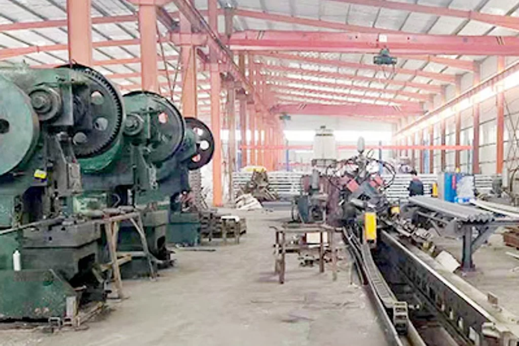
Production centres on forming the steel body and finishing the ball and eye geometry, followed by the specified galvanising process.
Inspection
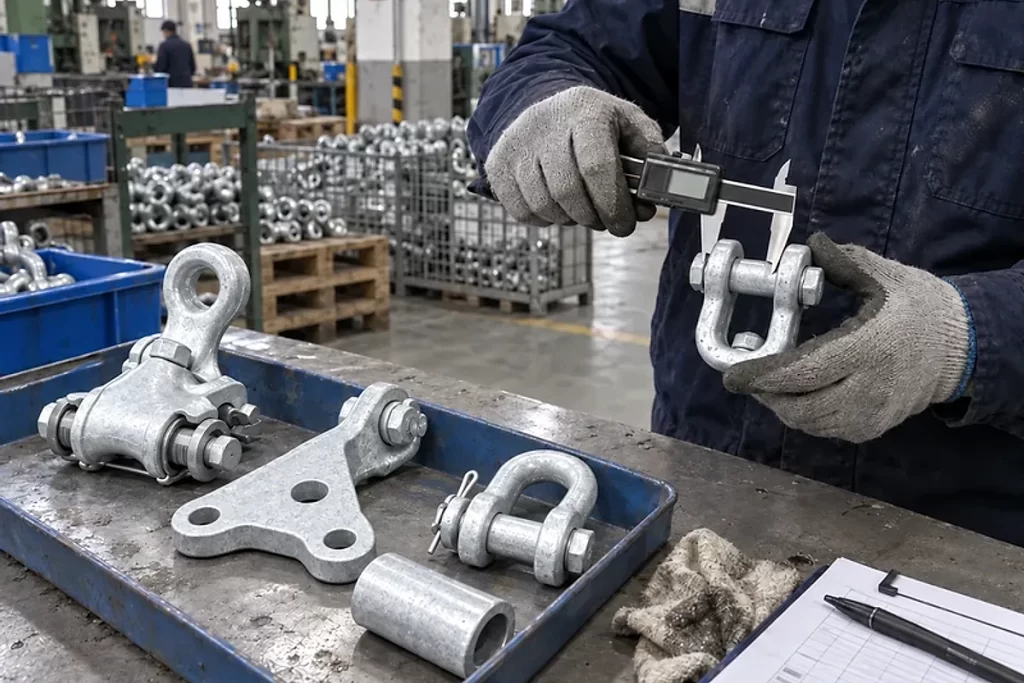
Inspection focuses on ball dimensions, eye diameter and thickness, coating condition and mechanical tests defined for the selected fitting.
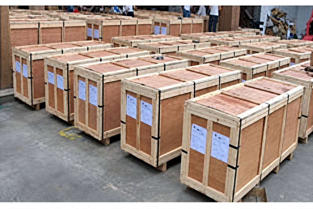
Packaging
Packaging protects the ball contact surface from impact and keeps fittings with different eye geometries separately identified.

Shipping
Dispatch preparation brings together model labels, quantities and packing details so each shipment can be matched to the order.
Frequently Asked Questions
Can the same ball eye fit every insulator of the same load rating?
No. Ball coupling designation and geometry must also match. Two fittings with the same stated failure load can have different connecting dimensions.
What changes when a ball clevis is used instead?
A ball clevis has a fork and pin at the hardware end. A ball eye has an eye that requires a compatible connecting component. The mating part determines which form fits.
Can ball eyes be used with composite insulators?
Yes, where the composite insulator has a matching socket end. The coupling designation and mechanical rating govern this connection; the housing material does not determine the fit.
What information is needed to enquire about ball eyes?
Send the insulator end-fitting drawing, required mechanical rating, eye and pin dimensions, assembly drawing, quantity and destination. Include the current part number when replacing an existing fitting.
Request for Free Consultation
Contact Information
Send us your cable requirements and our team will respond quickly with product recommendations, technical support and quotation details.