U-Type Anchor Shackles
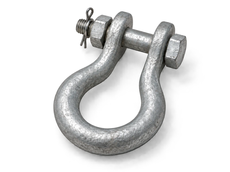
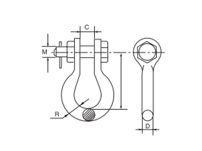
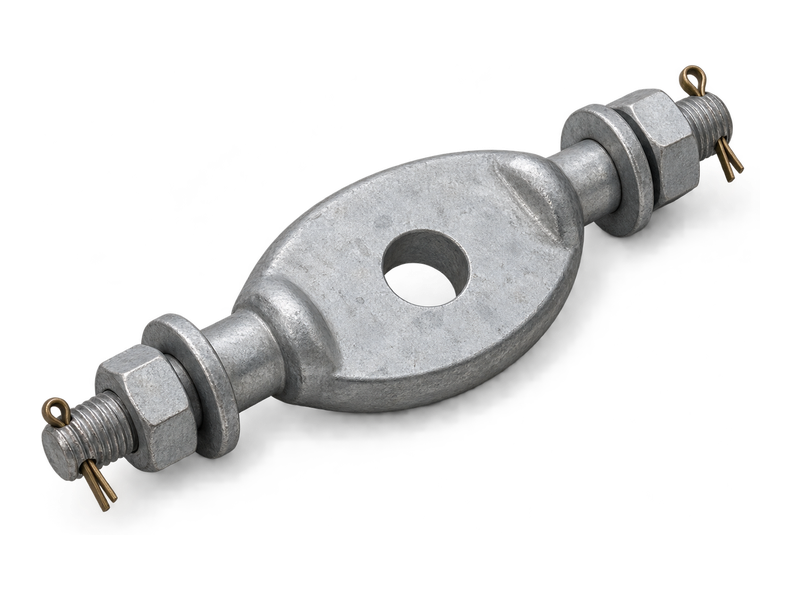
U-type anchor shackles connect tower attachments, insulator-string hardware and adjoining eye fittings on overhead lines. Their curved body creates space around the mating component, while a transverse pin or bolt closes the connection. These overhead line shackles provide a pin joint between fittings and can form part of an arrangement that changes the connection plane. U-series anchor shackles use a round-steel body with a hot-dip galvanised finish. The opening, body diameter, pin dimensions and internal curved space define how each model fits within the attachment assembly and carries the specified mechanical load.
Product Overview
The U-shaped body and its transverse fastening surround the connected eye or plate. The straight opening accommodates the mating thickness, while the curved section provides clearance around the joint. A hot-dip galvanised finish protects the steel surface against atmospheric corrosion.
Selecting anchor shackles for tower attachments involves the opening, pin fit, internal bend geometry and connection height. Where shackles are combined, their orientation determines the resulting connection plane. Movement and load direction are assessed for the complete arrangement.
Key Features
- Curved connection body: The U shape provides space around the connected eye or plate.
- Transverse fastening: A pin or bolt closes the joint through the mating component.
- Orientation transition: A paired-shackle arrangement can change the connection plane.
- Galvanised round steel: The zinc coating protects the round-steel body surface.
Product Applications
- Tower attachments: connects an insulator-string attachment to a compatible tower-side plate or eye fitting.
- Link-hardware transitions: joins compatible eyes and link fittings, including paired-shackle arrangements that change the connection plane.
Technical Specifications
U-shaped Anchor Shackle
| Item No. | Main dimensions(mm) | Rated Failure Load(kN) | Weight | ||||
|---|---|---|---|---|---|---|---|
| C | D | M | R | H | (kg) | ||
| U-7 | 20 | 16 | 16 | 22 | 80 | 70 | 0.52 |
| U-10 | 22 | 18 | 18 | 24 | 85 | 100 | 0.73 |
| U-12 | 24 | 20 | 22 | 30 | 90 | 120 | 1.01 |
| U-16 | 26 | 22 | 24 | 32 | 95 | 160 | 1.4 |
| U-21 | 30 | 24 | 27 | 36 | 100 | 210 | 2.12 |
| U-25 | 34 | 26 | 30 | 40 | 110 | 250 | 3 |
| U-30 | 38 | 30 | 36 | 46 | 130 | 300 | 4.33 |
| U-50 | 44 | 36 | 42 | 55 | 150 | 500 | 7 |
Request the Complete Data Sheet
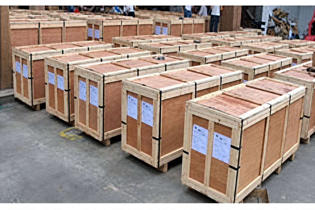
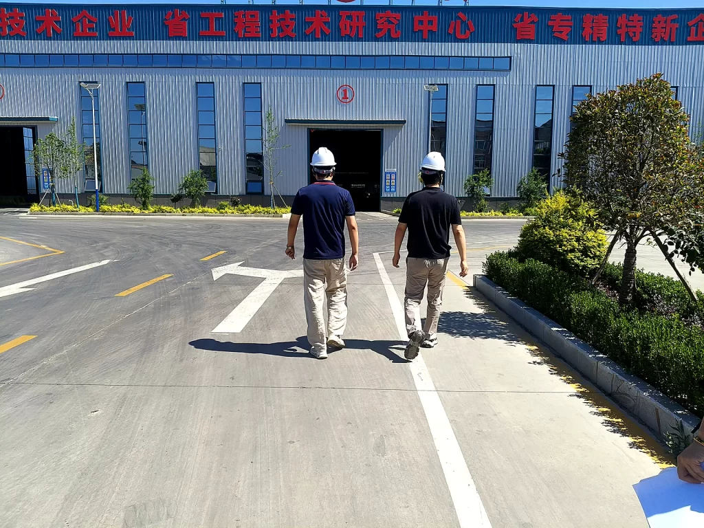
From Production to Delivery
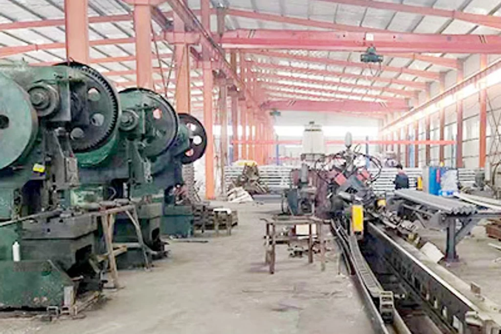
From raw material preparation to final shipmen, every stage is caretuly controled to ensure consistent conductor quality, reliable pertormance,and sae delivery. Our roduction,
inspection, packaging, and logistics processes are managed in accordance with applicable standards and project requirements.
Production
Production forms the round-steel body into the specified U geometry and prepares the ends for the pin or bolt connection.
Inspection
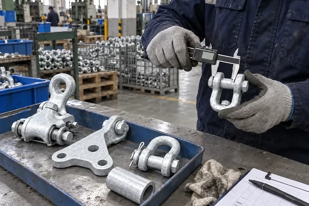
Inspection covers the opening, bend geometry, pin fit and retention, alongside coating condition and the specified mechanical tests.
Packaging
Packaging secures the matching pin or bolt and retaining parts with each shackle to keep the connection set together.
Shipping
Dispatch documentation records U-series models, quantities and package details for identification during transport and receipt.
Frequently Asked Questions
Which opening dimension should be provided?
Supply the mating part thickness and its connection drawing. The clear opening, pin size and internal curved space all affect whether it will fit.
Can two shackles change the plane of connection?
They can be used in such an arrangement, but clearances, contact and load direction must be assessed in the complete assembly.
Is the catalogue failure load a lifting capacity?
No. It is a mechanical failure-load designation for the listed fitting. A lifting rating and an allowable service load require their own applicable design and acceptance basis.
What information is needed to enquire about u-type anchor shackles?
Share the tower plate or mating eye drawing, required mechanical rating, opening and pin requirements, installation orientation and retention method. Include quantity, coating specification and delivery destination.
Request for Free Consultation
Contact Information
Send us your cable requirements and our team will respond quickly with product recommendations, technical support and quotation details.