Extension Rods

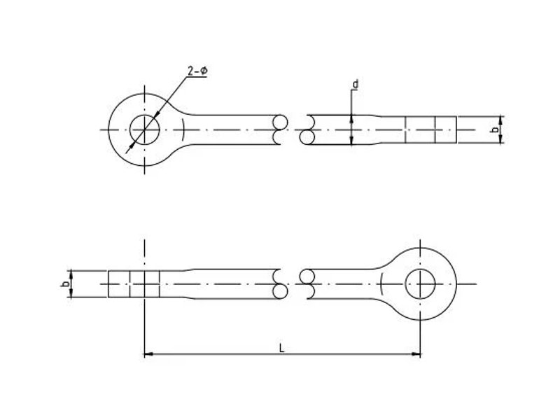
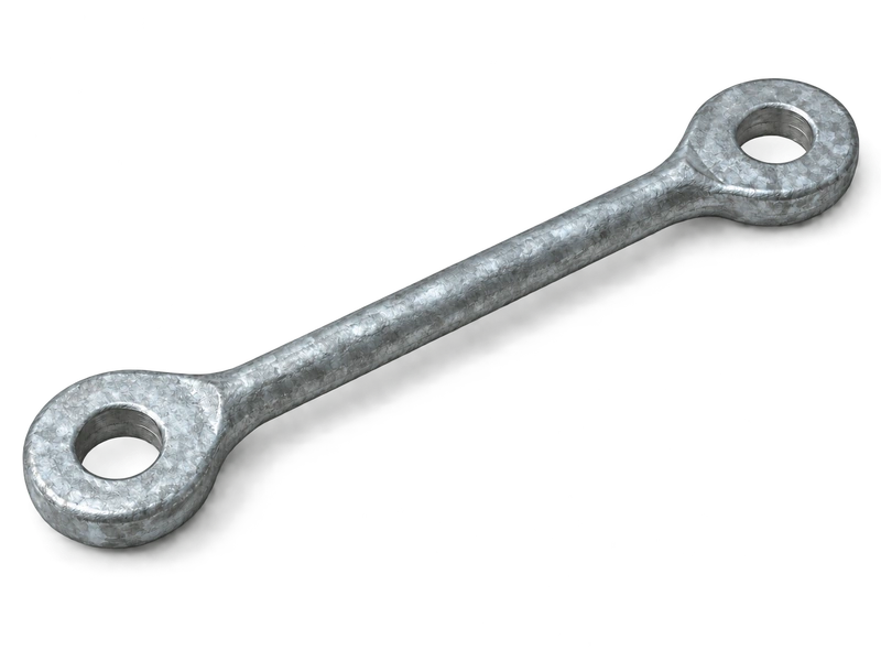
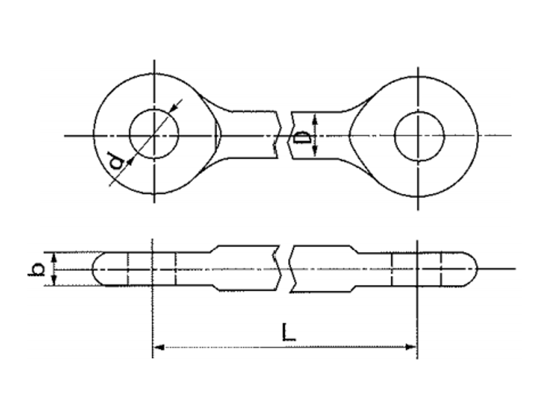
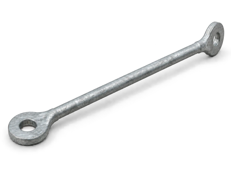
Extension rods for insulator strings create a fixed distance between two pin-connected fittings in overhead line suspension and tension assemblies. A steel rod body links the end eyes and carries the mechanical connection through the extended section. YL extension rods have end eyes in perpendicular planes, while YLP extension rods have eyes in the same plane, as shown in the product drawings. This difference allows the rod form to match the orientation of adjoining hardware. Eye-centre distance, hole dimensions, eye thickness and mechanical rating define the principal selection requirements for each arrangement.

Product Overview

The forged steel body spans the distance between the two eye joints and has a hot-dip galvanised finish. Connection length L is measured between the eye centres. Overall length also includes the material beyond those centres.

End-eye orientation determines how the rod meets the surrounding clevises or plate fittings. Selection combines this orientation with centre distance, pin fit and mechanical rating. Longer and shorter rods place neighbouring components at different positions within the string.

Key Features

  • Rod-type extension: The steel body spans the distance between two end-eye connections.
  • Two eye orientations: YL uses perpendicular eye planes; YLP uses a common plane.
  • Eye-centre length: L describes the distance between the connecting pin centres.
  • Galvanised forged steel: The surface coating protects the steel body against atmospheric corrosion.

Product Applications

  • Suspension-string extensions: provides a rod connection between fittings where the assembly requires a defined distance between pin joints.
  • Tension-string layouts: connects adjoining fittings across an extended section, with end eyes oriented to suit the surrounding hardware.

Technical Specifications

Extension Rods (Type YL)

Extension Rods (Type YL)

Catalog No.Dimensions(mm)Rated Failure Load(kN)Weight(kg)
DdbL
YL-10121820161201000.8
YL-10401820164001001.1
YL-10501820165001001.4
YL-10691820166901001.9
YL-1010018201610001002.2
YL-12432224184301201.6
YL-16432226184301601.6
YL-20432430204302003
Extension Rods (Type YLP)

Extension Rods (Type YLP)

Catalog No.Dimensions(mm)Rated Failure Load(kN)Weight (kg)
DdbL
YLP-162602426202601601.6
YLP-168502426208501603.7
YLP-169102426209101603.9
YLP-169702426209701604.1
YLP-169902426209901604.3
YLP-258553033308552506.2
YLP-259153033309152506.6
YLP-259353033309352506.7

Request the Complete Data Sheet

If you need a specific product catalogue or related standard file, please contact us.

From Production to Delivery

From raw material preparation to final shipmen, every stage is caretuly controled to ensure consistent conductor quality, reliable pertormance,and sae delivery. Our roduction,
inspection, packaging, and logistics processes are managed in accordance with applicable standards and project requirements.

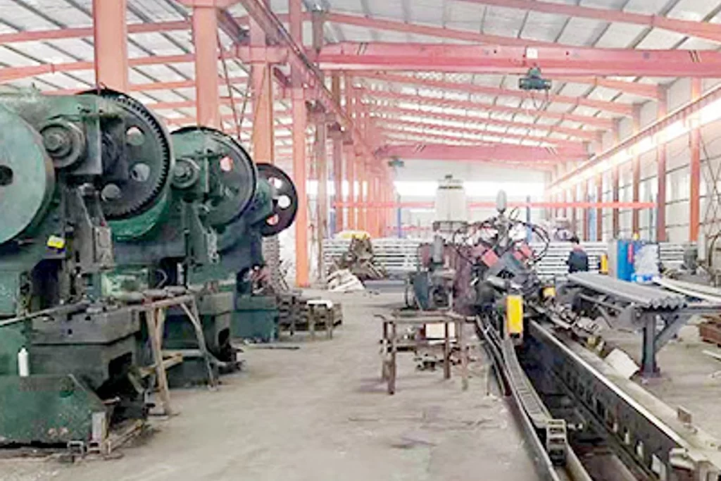
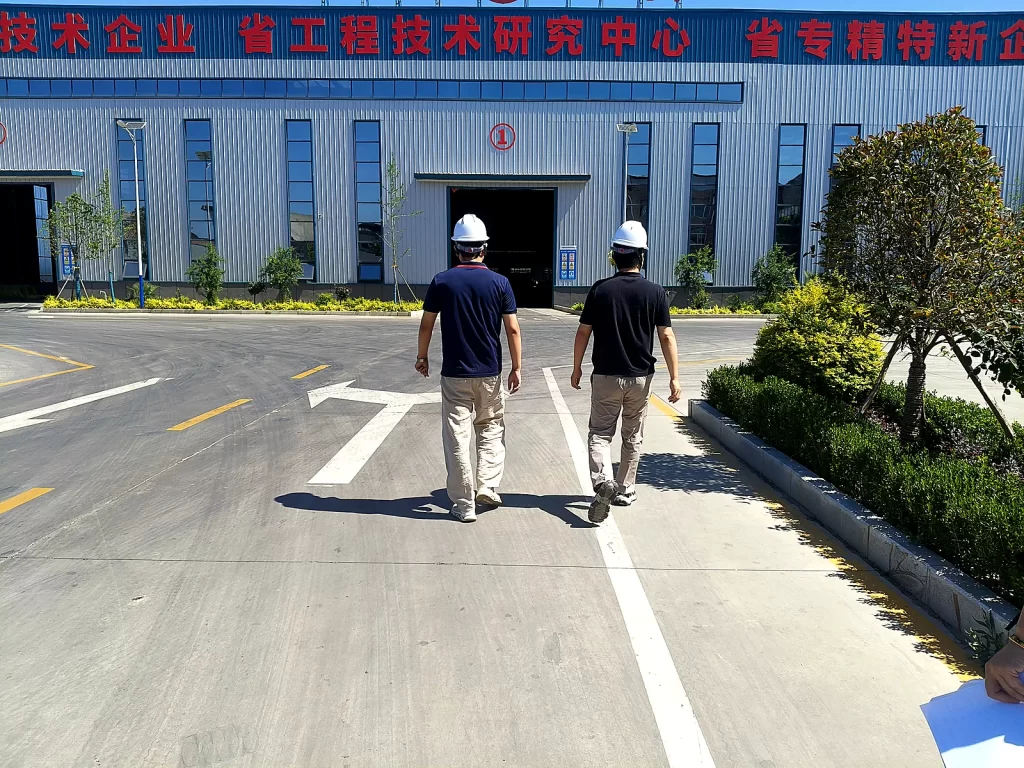
hardware production workshop

Production

Production forms the forged body and end eyes, establishes their relative orientation and finishes the connection holes before the specified surface treatment.

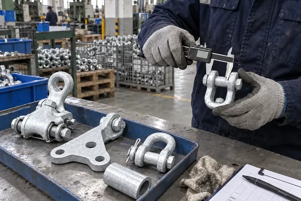
Dimensional inspection of galvanized overhead line hardware

Inspection

Inspection measures eye-centre distance, end orientation, hole diameter and eye thickness, with coating and mechanical checks tied to the model specification.

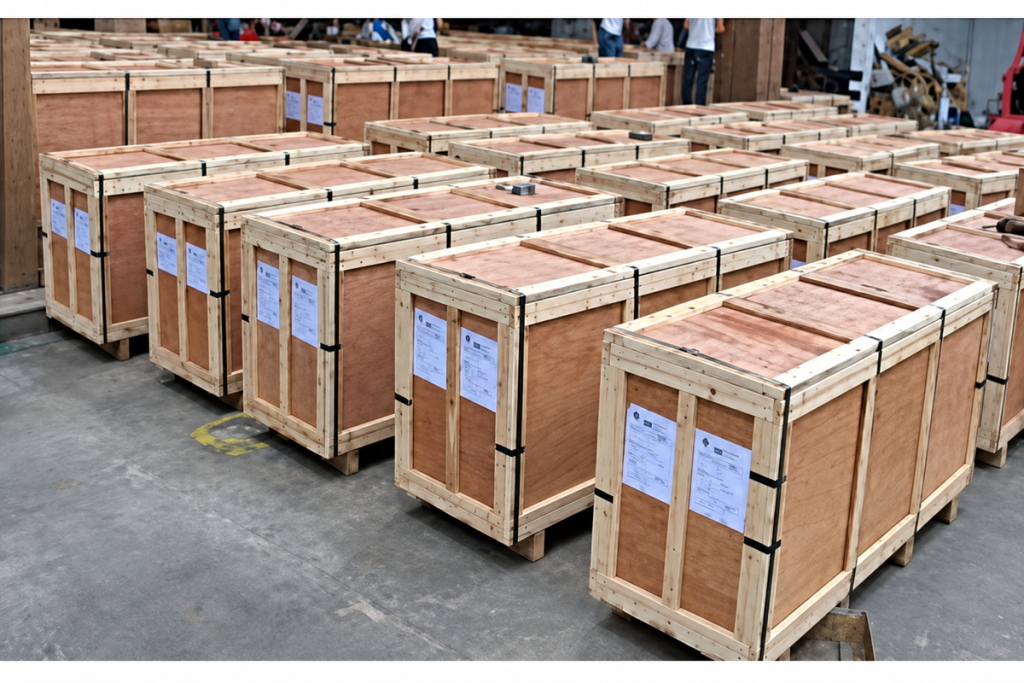
hardware packed in wooden crates for export shipment

Packaging

Packing supports the rods along their length and separates YL and YLP forms to preserve identification and protect the end connections.

Wooden crates of electrical hardware loaded for container shipment

Shipping

Dispatch planning accounts for packed rod lengths, quantities and handling arrangements, with each end-orientation variant separately labelled.

Frequently Asked Questions

What is the practical difference between YL and YLP?

The illustrated YL forms have perpendicular end-eye planes; the YLP forms have both eyes in one plane. This affects the orientation of the adjoining clevises and pins within the string.

In the supplied drawings L runs between the eye centres. Overall length includes the material beyond those centres and should be checked separately if space is restricted.

Only after the assembly geometry is reviewed. A change in length can affect component positions and clearances even when the catalogue failure-load values are equal.

Send the required eye-centre distance, end-eye orientation, hole diameter, eye thickness and mechanical rating. Include both adjoining fittings, the assembly drawing, quantity and destination.

Request for Free Consultation

Contact Information

Send us your cable requirements and our team will respond quickly with product recommendations, technical support and quotation details.

Explore More

Related Products
liycy-tp-cable
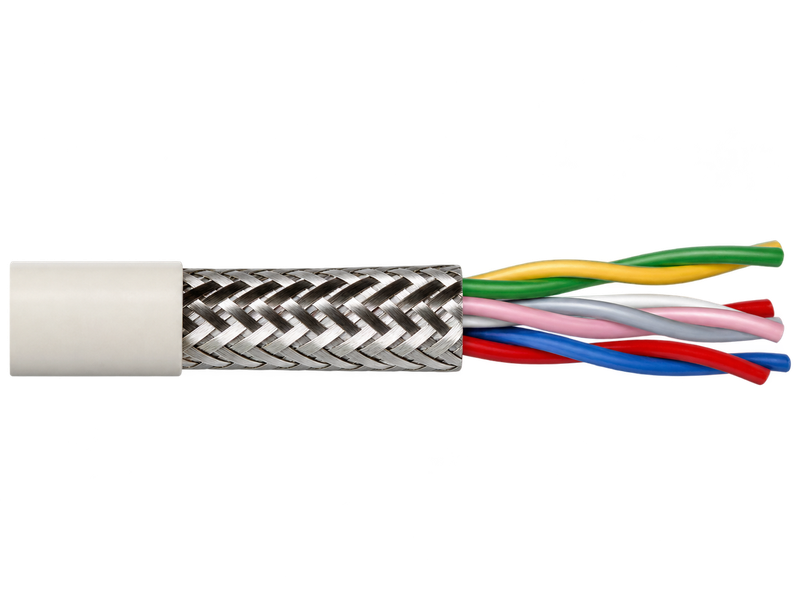
LiYCY Cable for Screened Signal and Control Wiring
BS 6346 PVC Insulated Armoured Cable 6001000 V
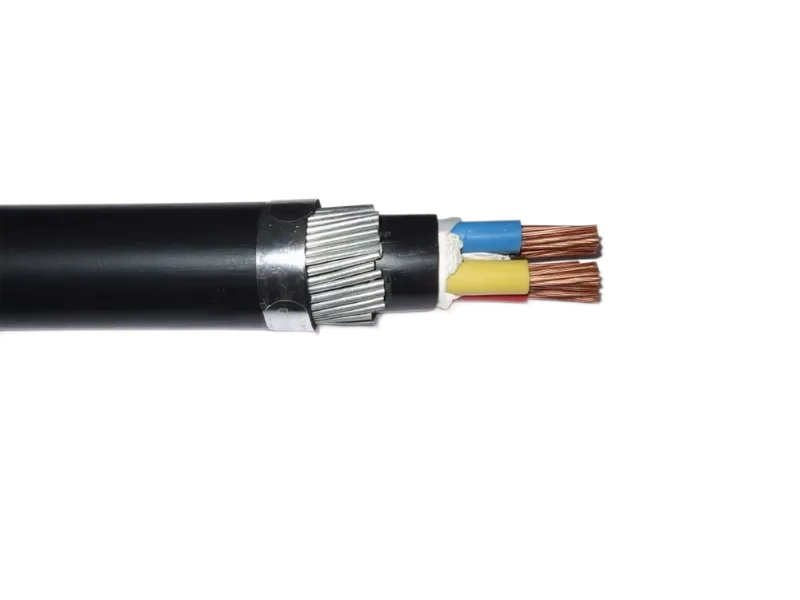
BS 5467 XLPE Insulated Armoured Power Cable
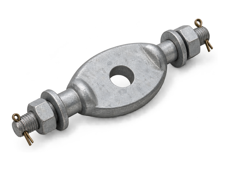
GD link fitting with central eye and transverse bolted connections for overhead line hardware
Twisted Link Plates — Type GD
Compatible Hardware
liycy-tp-cable
LiYCY Cable for Screened Signal and Control Wiring
BS 6346 PVC Insulated Armoured Cable 6001000 V
BS 5467 XLPE Insulated Armoured Power Cable
GD link fitting with central eye and transverse bolted connections for overhead line hardware
Twisted Link Plates — Type GD
Knowledge Articles
AAC vs AAAC vs ACSR: Which Overhead Conductor to Choose?
Customer Visits Our Factory for Product Inspection and Quality Verification
AAAC all aluminium alloy conductor stranded wire
AAAC Conductor Selection Guide: How to Choose the Right AAAC for Overhead Lines

For Immediate Assistance, Please Contact us Now!