Medium-Voltage Aerial Bundled Cable (MV ABC)
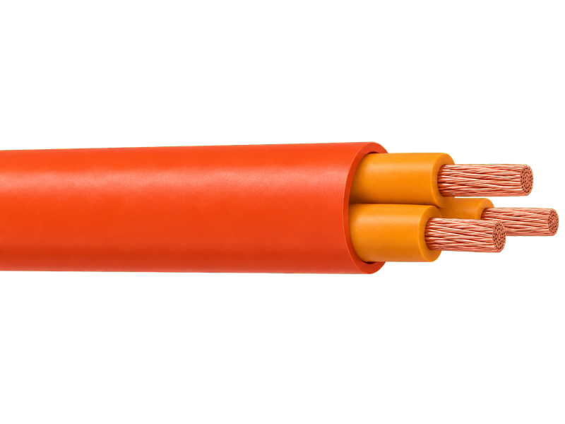
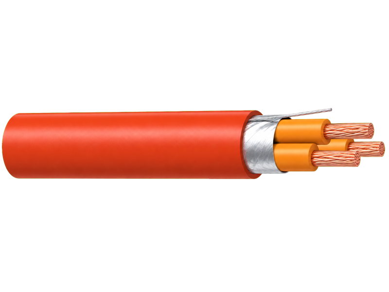
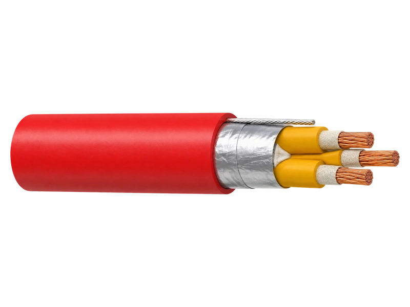
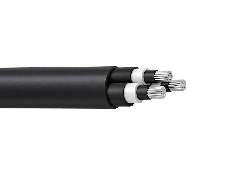
MV aerial bundled cable combines three XLPE-insulated aluminium phase cores around a dedicated support conductor for compact medium-voltage overhead distribution. Available voltage classes include 6.35/11 kV, 12.7/22 kV and project-specific 19/33 kV designs. The product range includes metallic-screened and non-metallic-screened AS/NZS 3599 series constructions, together with overhead designs that reference IEC 60502 alongside a controlling utility or project specification.
Product Overview
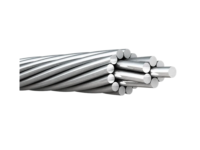
The phase-core screen system and the mechanical support system are separate selection decisions. Metallic-screened variants include a copper-wire screen and require a defined earthing and termination arrangement. Non-metallic-screened variants use semiconductive layers without the same metallic screen. The support conductor carries the suspended mechanical load and may differ in material and strength between constructions, affecting span design and support fittings.
AS/NZS 3599.1 applies to metallic-screened aerial bundled cables, while AS/NZS 3599.2 covers non-metallic-screened designs in the stated voltage range. IEC 60502-2 does not by itself define a cable for overhead networks, so any IEC-referenced MV ABC also requires a utility or project specification for the complete bundle, support member and tests. Buyers should provide the voltage, screen system, phase size, support duty, spans, earthing, terminations and required documentation.
Key Features
- Three-phase bundled construction:Three compacted aluminium phase conductors create a defined three-phase overhead bundle, reducing route width compared with separately supported insulated phase cables in the intended system.
- Screen-system options:Metallic-screened phase cores include a copper-wire screen, whereas non-metallic-screened designs use a different semiconductive-layer arrangement; the selected system determines earthing and termination requirements.
- Dedicated support conductor:A central support conductor carries the suspended mechanical load; selecting its material, size and strength with the phase cores keeps span design and support fittings aligned with bundle mass.
- Voltage- and screen-specific tables:Voltage- and screen-specific tables retain the correct phase-core diameter, bundle mass and layer system, giving buyers the dimensional basis needed for terminations, clamps, reels and route planning.
Product Applications
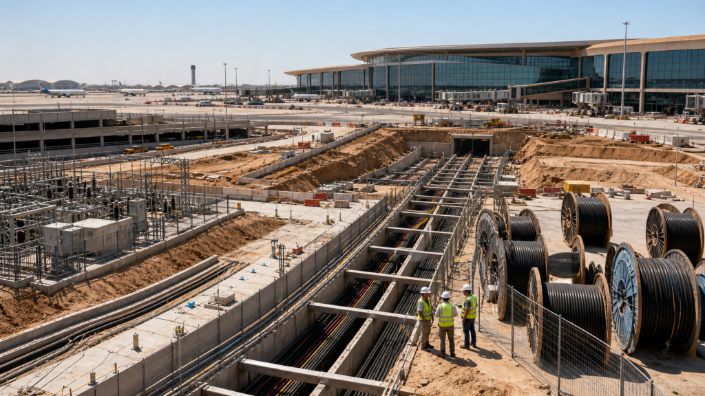
- 35/11 kV and 12.7/22 kV overhead distribution feeders designed around screened or non-screened AS/NZS 3599.1 bundles
- Project-specific 19/33 kV pole routes where the utility schedule defines the overhead construction, support member, tests and accessories
- Compact utility and industrial feeders requiring three insulated phase cores and a dedicated mechanical support conductor in one bundle
Technical Specifications
AS/NZS 3599.1 6.35/11 kV AL/XLPE/HDPE Non-Screened — Construction Parameters
| Number of Cores x Nominal Cross Section | Phase Conductor | Messenger Suspension Unit | Nominal Sectional Area | Breaking Load | |||
|---|---|---|---|---|---|---|---|
| Diameter of Conductor | Thickness of Insulation | Thickness of Insulation Screen | Thickness of Sheath | Stranding | |||
| No.×mm^2 | mm | mm | mm | mm | No.×mm | mm^2 | KN |
| 3x35 | 6.9 | 3.4 | 0.8 | 1.2 | 7/4.75 | 52.4 | 1370 |
| 3x50 | 8.1 | 3.4 | 0.8 | 1.2 | 7/4.75 | 54.6 | 1530 |
| 3x70 | 9.7 | 3.4 | 0.8 | 1.2 | 7/4.75 | 57.8 | 1790 |
| 3x95 | 11.4 | 3.4 | 0.8 | 1.2 | 7/4.75 | 61.3 | 2100 |
| 3x120 | 12.8 | 3.4 | 0.8 | 1.2 | 19/3.50 | 67.3 | 2540 |
| 3x150 | 14.2 | 3.4 | 0.8 | 1.2 | 19/3.50 | 70.1 | 2840 |
| 3x185 | 15.7 | 3.4 | 0.8 | 1.2 | 19/3.50 | 73.1 | 3190 |
Note: *Other cross-sections can be offered upon request.
AS/NZS 3599.1 6.35/11 kV AL/XLPE/CWS/HDPE Screened — Construction Parameters
| Number of Cores x Nominal Cross Section | Diameter of Conductor | Thickness of Insulation | Thickness of Insulation Screen | Copper Wire Screen Stranding | Thickness of Sheath | Galvanized Steel Wire Stranding | Nominal Sectional Area | Breaking Load |
|---|---|---|---|---|---|---|---|---|
| No.×mm^2 | mm | mm | mm | No.×mm | mm | No.×mm | mm^2 | KN |
| Light Duty Screen | ||||||||
| 3x35 | 6.9 | 3.4 | 0.8 | 25/0.85 | 1.8 | 7/2.00 | 54.1 | 1820 |
| 3x35 | 6.9 | 3.4 | 0.8 | 25/0.85 | 1.8 | 19/2.00 | 58.1 | 2130 |
| 3x50 | 8.1 | 3.4 | 0.8 | 25/0.85 | 1.8 | 19/2.00 | 60.4 | 2300 |
| 3x70 | 9.7 | 3.4 | 0.8 | 25/0.85 | 1.8 | 19/2.00 | 63.6 | 2570 |
| 3x95 | 11.4 | 3.4 | 0.8 | 25/0.85 | 1.8 | 19/2.00 | 67.0 | 2900 |
| 3x120 | 12.8 | 3.4 | 0.8 | 25/0.85 | 1.8 | 19/2.00 | 69.8 | 3190 |
| 3x150 | 14.2 | 3.4 | 0.8 | 25/0.85 | 1.9 | 19/2.00 | 73.0 | 3530 |
| 3x185 | 15.7 | 3.4 | 0.8 | 25/0.85 | 1.9 | 19/2.00 | 76.0 | 3890 |
| Heavy Duty Screen | ||||||||
| 3x35 | 6.9 | 3.4 | 0.8 | 40/0.85 | 1.8 | 7/2.00 | 54.1 | 2050 |
| 3x35 | 6.9 | 3.4 | 0.8 | 40/0.85 | 1.8 | 19/2.00 | 58.1 | 2360 |
| 3x50 | 8.1 | 3.4 | 0.8 | 23/1.35 | 1.8 | 19/2.00 | 62.4 | 2820 |
| 3x70 | 9.7 | 3.4 | 0.8 | 32/1.35 | 1.8 | 19/2.00 | 65.6 | 3440 |
| 3x95 | 11.4 | 3.4 | 0.8 | 39/1.35 | 1.8 | 19/2.00 | 69.0 | 4030 |
| 3x120 | 12.8 | 3.4 | 0.8 | 39/1.35 | 1.8 | 19/2.00 | 71.8 | 4320 |
| 3x150 | 14.2 | 3.4 | 0.8 | 39/1.35 | 1.9 | 19/2.00 | 75.0 | 4670 |
| 3x185 | 15.7 | 3.4 | 0.8 | 39/1.35 | 1.9 | 19/2.00 | 78.0 | 5020 |
Note: *Other cross-sections can be offered upon request.
AS/NZS 3599.1 12.7/22 kV AL/XLPE/HDPE Non-Screened — Construction Parameters
| Number of Cores x Nominal Cross Section | Phase Conductor | Messenger Suspension Unit | Nominal Sectional Area | Breaking Load | |||
|---|---|---|---|---|---|---|---|
| Diameter of Conductor | Thickness of Insulation | Thickness of Insulation Screen | Thickness of Sheath | Stranding | |||
| No.×mm^2 | mm | mm | mm | mm | No.×mm | mm^2 | KN |
| 3x35 | 6.9 | 5.5 | 0.8 | 1.2 | 7/4.75 | 61.0 | 1780 |
| 3x50 | 8.1 | 5.5 | 0.8 | 1.2 | 7/4.75 | 63.3 | 1970 |
| 3x70 | 9.7 | 5.5 | 0.8 | 1.2 | 7/4.75 | 66.5 | 2260 |
| 3x95 | 11.4 | 5.5 | 0.8 | 1.2 | 7/4.75 | 69.9 | 2600 |
| 3x120 | 12.8 | 5.5 | 0.8 | 1.2 | 19/3.50 | 75.9 | 3070 |
| 3x150 | 14.2 | 5.5 | 0.8 | 1.2 | 19/3.50 | 78.7 | 3390 |
| 3x185 | 15.7 | 5.5 | 0.8 | 1.2 | 19/3.50 | 81.7 | 3760 |
Note: *Other cross-sections can be offered upon request.
AS/NZS 3599.1 12.7/22 kV AL/XLPE/CWS/HDPE Screened — Construction Parameters
| Number of Cores x Nominal Cross Section | Diameter of Conductor | Thickness of Insulation | Thickness of Insulation Screen | Copper Wire Screen Stranding | Thickness of Sheath | Galvanized Steel Wire Stranding | Nominal Sectional Area | Breaking Load |
|---|---|---|---|---|---|---|---|---|
| No.×mm^2 | mm | mm | mm | No.×mm | mm | No.×mm | mm^2 | KN |
| Light Duty Screen | ||||||||
| 3x35 | 6.9 | 5.5 | 0.8 | 25/0.85 | 1.8 | 7/2.00 | 62.7 | 2280 |
| 3x35 | 6.9 | 5.5 | 0.8 | 25/0.85 | 1.8 | 19/2.00 | 66.7 | 2580 |
| 3x50 | 8.1 | 5.5 | 0.8 | 25/0.85 | 1.8 | 19/2.00 | 69.0 | 2780 |
| 3x70 | 9.7 | 5.5 | 0.8 | 25/0.85 | 1.9 | 19/2.00 | 72.6 | 3110 |
| 3x95 | 11.4 | 5.5 | 0.8 | 25/0.85 | 1.9 | 19/2.00 | 76.0 | 3460 |
| 3x120 | 12.8 | 5.5 | 0.8 | 25/0.85 | 2.0 | 19/2.00 | 79.2 | 3810 |
| 3x150 | 14.2 | 5.5 | 1.0 | 25/0.85 | 2.0 | 19/2.00 | 82.8 | 4230 |
| 3x185 | 15.7 | 5.5 | 1.0 | 25/0.85 | 2.1 | 19/2.00 | 86.2 | 4650 |
| Heavy Duty Screen | ||||||||
| 3x35 | 6.9 | 5.5 | 0.8 | 40/0.85 | 1.8 | 7/2.00 | 62.7 | 2510 |
| 3x35 | 6.9 | 5.5 | 0.8 | 40/0.85 | 1.8 | 19/2.00 | 66.7 | 2810 |
| 3x50 | 8.1 | 5.5 | 0.8 | 23/1.35 | 1.8 | 19/2.00 | 71.0 | 3300 |
| 3x70 | 9.7 | 5.5 | 0.8 | 32/1.35 | 1.9 | 19/2.00 | 74.6 | 3970 |
| 3x95 | 11.4 | 5.5 | 0.8 | 39/1.35 | 1.9 | 19/2.00 | 78.0 | 4600 |
| 3x120 | 12.8 | 5.5 | 0.8 | 39/1.35 | 2.0 | 19/2.00 | 81.2 | 4950 |
| 3x150 | 14.2 | 5.5 | 1.0 | 39/1.35 | 2.0 | 19/2.00 | 84.8 | 5360 |
| 3x185 | 15.7 | 5.5 | 1.0 | 39/1.35 | 2.1 | 19/2.00 | 88.2 | 5790 |
IEC 60502 6.35/11 kV ABC — Construction Parameters
| Number of Cores x Nominal Cross Section | Phase Conductor | Messenger Suspension Unit | Continuous current rating at 300C ambient temp | ||||
|---|---|---|---|---|---|---|---|
| Stranding | Nominal Sectional Area | Maximum Conductor Resistance | Stranding | Nominal Sectional Area | Breaking Load | ||
| No.×mm^2 | No.×mm | mm^2 | Ω/Km | No.×mm | mm^2 | KN | A |
| 3X50 + 1X25 | 19/1.78 | 50 | 0.641 | 7/3.0 | 50 | 60 | 116 |
| 3X70 + 1X50 | 19/.14 | 70 | 0.443 | 7/3.15 | 50 | 62 | 210 |
| 3X95+ 1X50 | 19/2.52 | 95 | 0.32 | 7/3.0 | 50 | 60 | 173 |
| 3X185+1X120 | 37/2.52 | 185 | 0.164 | 7/4.67 | 120 | 150 | 259 |
| 3X150 +1X50 | 37/2.25 | 150 | 0.206 | 7/3.15 | 50 | 62 | 365 |
| 3X240 +1X50 | 61/2.25 | 240 | 0.125 | 7/3.15 | 50 | 62 | 500 |
Note: *Other cross-sections can be offered upon request.
IEC 60502 19/33 kV ABC — Construction Parameters
| Number of Cores x Nominal Cross Section | Phase Conductor | Messenger Suspension Unit | Continuous current rating at 300C ambient temp | ||||
|---|---|---|---|---|---|---|---|
| Stranding | Nominal Sectional Area | Maximum Conductor Resistance | Stranding | Nominal Sectional Area | Breaking Load | ||
| No.×mm^2 | No.×mm | mm^2 | Ω/Km | No.×mm | mm^2 | KN | A |
| 3X50 + 1X50 | 19/1.78 | 50 | 0.641 | 7/3.0 | 50 | 60 | 165 |
| 3X150+ 1X50 | 37/2.25 | 150 | 0.206 | 7/3.0 | 50 | 60 | 315 |
| 3X185+1X70 | 37/2.52 | 185 | 0.164 | 7/3.57 | 70 | 91 | 355 |
| 3X70 +1X50 | 19/2.14 | 7 | 0.443 | 7/3.15 | 50 | 62 | 250 |
| 3X150 +1X50 | 37/2.25 | 150 | 0.206 | 7/3.15 | 50 | 62 | 370 |
Note: *Other cross-sections can be offered upon request.
Request the Complete Data Sheet
From Production to Delivery
From raw material preparation to final shipmen, every stage is caretuly controled to ensure consistent conductor quality, reliable pertormance,and sae delivery. Our roduction,
inspection, packaging, and logistics processes are managed in accordance with applicable standards and project requirements.
Production
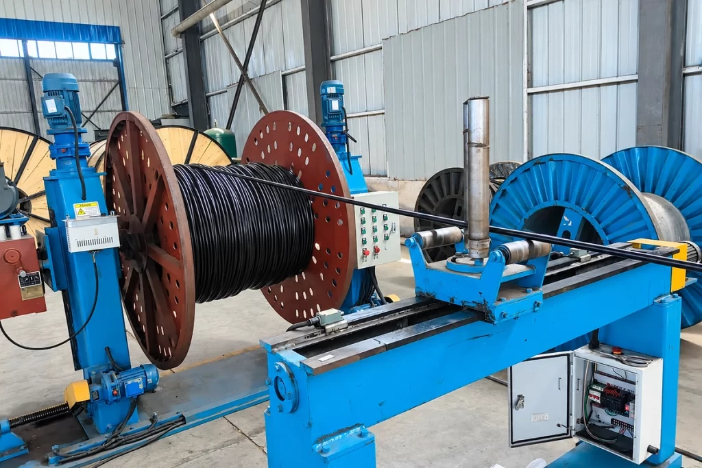
Each compact aluminium phase conductor receives the specified conductor screen, XLPE insulation and screen or sheath layers, after which three completed cores are laid around the selected mechanical support member.

Inspection
Inspection covers phase-core layer dimensions, conductor resistance, screen continuity where applicable, support construction, bundle lay, finished dimensions and the electrical or mechanical tests listed in the project programme.
Packaging
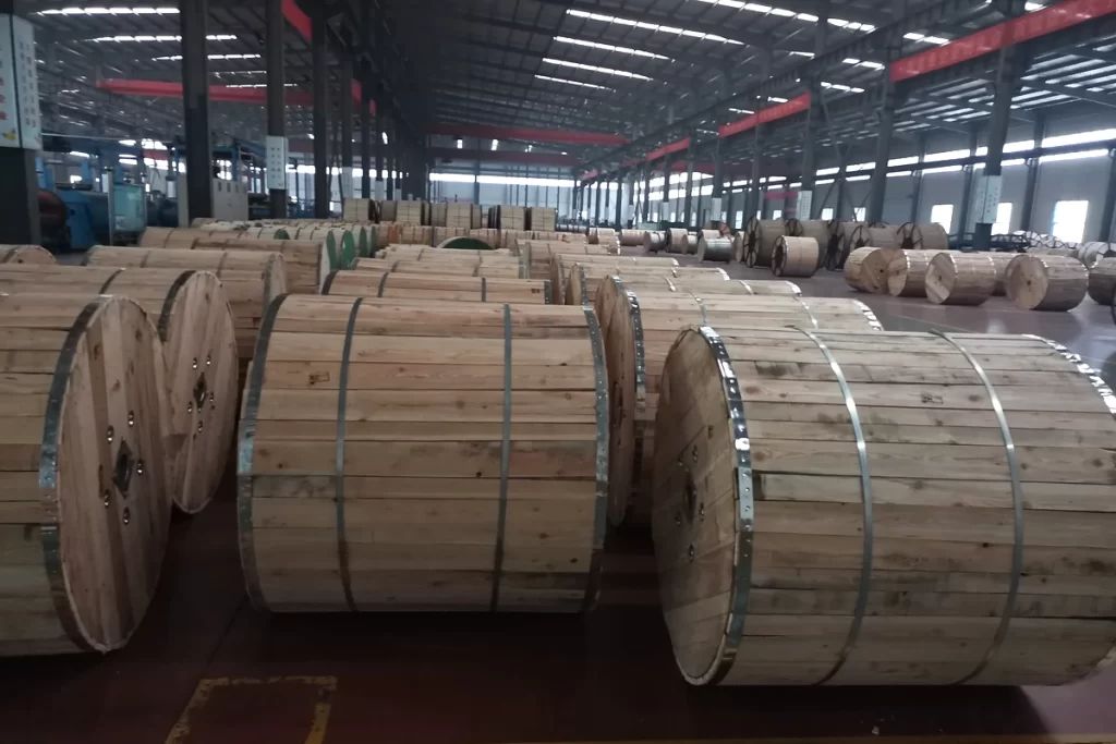
Large reels, end sealing and screen protection are selected for the bundle diameter and mass, with delivery lengths planned around the customer’s pulling, stringing, lifting and termination sequence.
Shipping
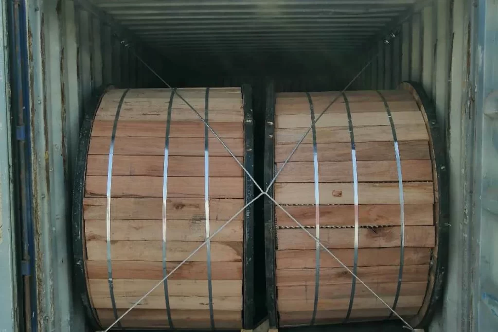
Drum and shipping records identify voltage, screened or non-screened construction, phase size, support conductor, standard or project specification, length and batch, supporting accurate site allocation and traceability.
Frequently Asked Questions
How do I choose between metallic-screened and non-metallic-screened MV ABC?
The governing utility specification, earthing arrangement and termination design determine the screen system. AS/NZS 3599.1 applies to metallic-screened cable and AS/NZS 3599.2 to non-metallic-screened cable. Send the voltage and network requirements, and we will identify the corresponding phase-core and support construction in the quotation.
What information is needed to select the support conductor?
Please provide span lengths, bundle mass, tensile and sag criteria, environmental loading and proposed fittings. We can show the support-member options in the relevant construction and include the selected material and size in the offer, keeping mechanical duty separate from phase conductor area.
Can you supply terminations for the MV phase cores?
Termination options can be discussed once the voltage, conductor area, insulation diameter, screen and sheath system, earthing method and connected equipment are known. We can list compatible options with the cable for technical review, reducing the chance that accessories are selected from voltage alone.
Does an IEC 60502 reference fully define overhead MV ABC?
IEC 60502-2 generally excludes overhead networks, so an IEC-referenced product also needs a project or utility schedule covering the overhead assembly and tests. Share that document with us and we will use its construction language in the quotation rather than presenting the IEC reference as the only design basis.
Can project-specific reel lengths be arranged for a large MV bundle?
Reel planning can consider route sections, bundle diameter and mass, bend limits, lifting capacity and installation equipment. Provide the proposed length schedule and we can discuss practical delivery lengths and drum identification before the commercial and production programme is finalised.
What should I include in an MV ABC enquiry?
Please send voltage, governing standard or project specification, screened or non-screened design, phase size, support material and size, span and tension data, earthing, terminations, quantity, reel lengths and test documents. A route or single-line drawing will help us organise the offer.
Request for Free Consultation
Contact Information
Send us your cable requirements and our team will respond quickly with product recommendations, technical support and quotation details.