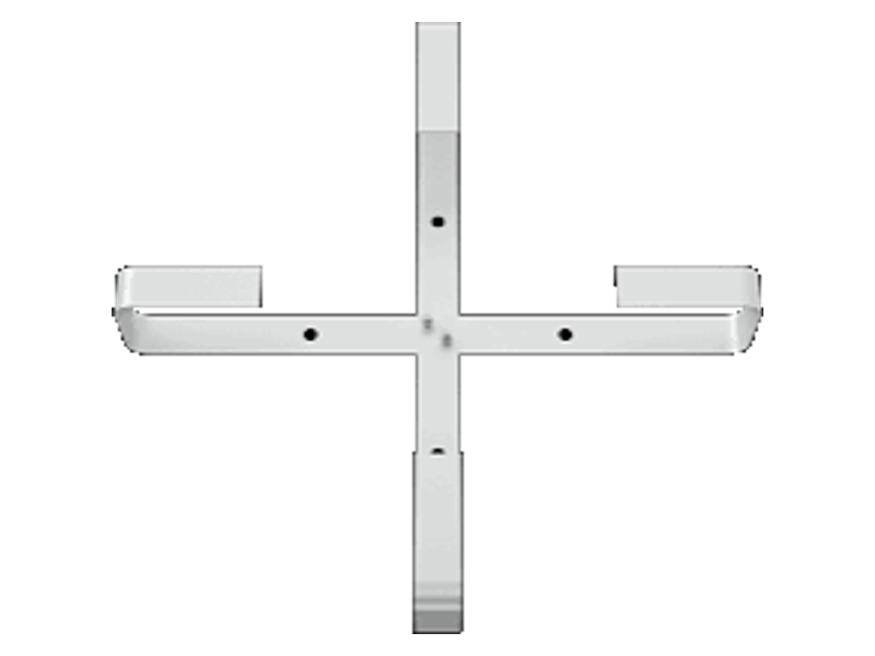
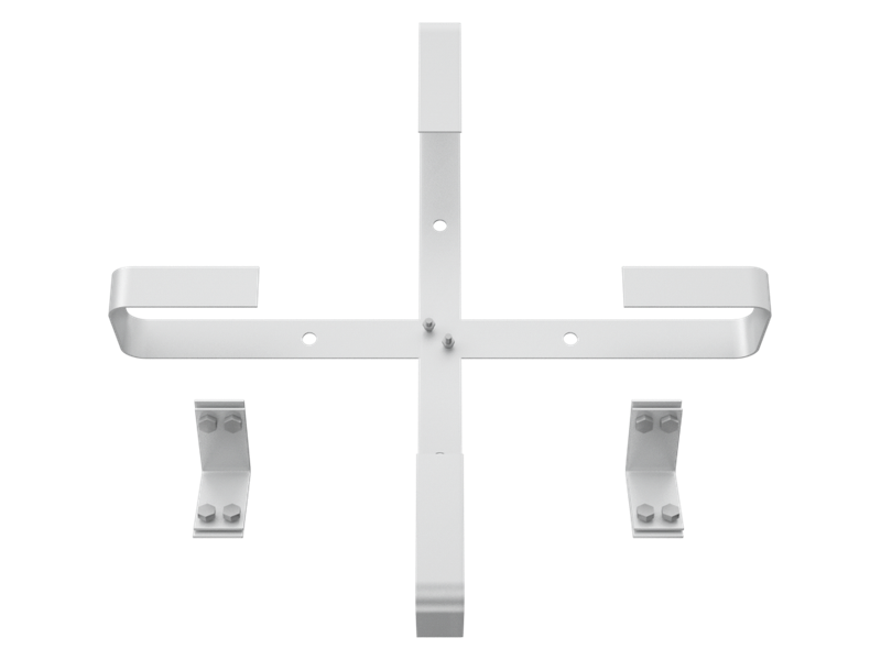
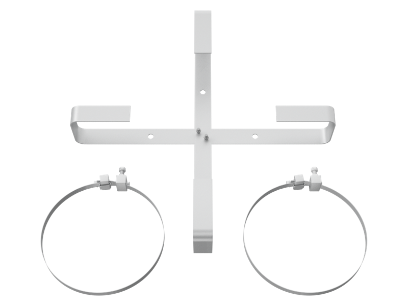
OPGW Cable Storage Assembly for Towers and Poles
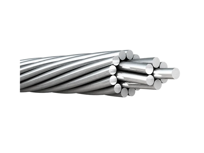
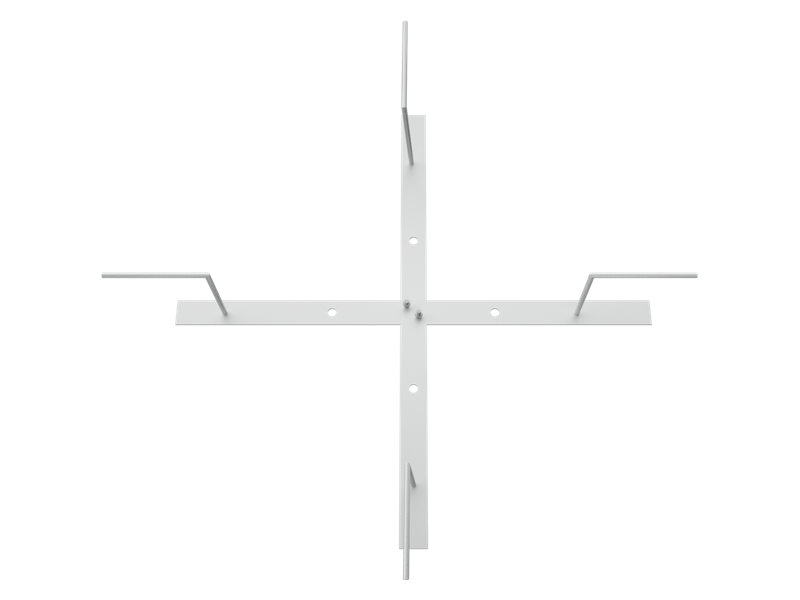
The OPGW Cable Storage Assembly for Towers and Poles, also known as an OPGW slack storage bracket, OPGW cable storage bracket or OPGW coil bracket, organises reserved optical ground wire for splicing, maintenance and future re-entry. The Cable Storage Assembly is available in external-coil and inserted arrangements for both structure types. Selection considers cable diameter, reserve length, minimum bending requirement, available mounting space and the position of the splice closure.
Product Overview
The Cable Storage Assembly manages reserved cable mechanically; it does not protect fibre splices. That function belongs to the Splice Closure. An external-coil arrangement keeps the stored loop outside the structure for direct access, while an inserted arrangement uses available internal structural space. Tower versions use small-clamp mounting, and pole versions use pole-specific supports or stainless-steel banding. These variants address different access and mounting conditions rather than different optical functions.
The storage loop must follow the minimum bending requirement stated for the OPGW and must not obstruct climbing routes, electrical clearances or adjacent fittings. Buyers should provide the cable outside diameter, required reserve length, minimum bend requirement, tower-member or pole dimensions, mounting height, closure position and available space. This information allows the OPGW cable storage hardware, downlead route and joint location to be reviewed as one arrangement. For an external coil OPGW slack storage bracket or an inserted OPGW cable storage bracket for joint structures, the structure drawing is especially useful because usable space and mounting access determine the practical layout.
Key Features
- Controlled slack management:The Cable Storage Assembly keeps reserved OPGW organised at the joint structure, supporting later splicing or maintenance without leaving an uncontrolled loop.
- External-coil and inserted options:Separate arrangements suit different access and structural-space conditions while maintaining the required cable bend geometry.
- Tower and pole mounting ranges:Tower sets use small clamps, while pole arrangements can use supports and stainless-steel bands selected for the actual pole diameter.
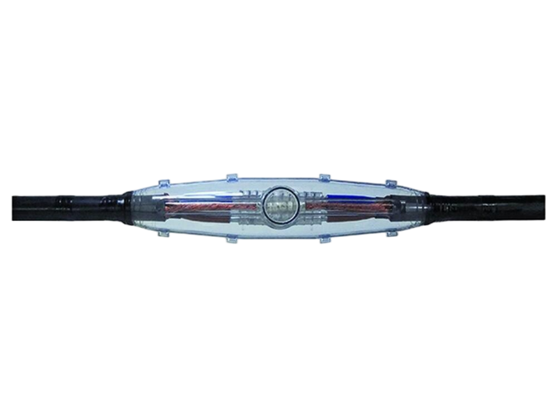
- Coordinated joint layout:The storage position can be planned with Downlead Clamps and the Splice Closure, helping avoid abrupt bends, obstructed access and conflicting hardware.
Product Applications
- Used at OPGW splice locations on towers and poles where reserved cable length is required for installation and maintenance purposes.
- Applied in transmission line projects requiring organized management of spare OPGW cable near joint structures.
- Suitable for new installations, expansion projects and maintenance works involving existing OPGW systems.
Technical Specifications
OPGW Cable Storage Assembly
| ltem | Type | Mounting Accessory |
|---|---|---|
| Cable Storage Assembly for Tower | TYL | small clamp |
| TYLN | ||
| Cable Storage Assembly for Pole | GYL*** | pillar for pole |
| GYLN*** |
Stainless Steel Strip
| Name | Type | Pole Dia.(mm) |
|---|---|---|
| Stainless Steel Strip | BDL-1 | 150-300 |
| BDL-2 | 301-400 | |
| BDL-3 | 401-600 | |
| BDL-4 | 601-800 | |
| BDL-5 | 801-1000 |
Small Clamp for Tower
| Name | Type | (mm) | Material | Remark |
|---|---|---|---|---|
| Small Clamp | YJB-*** | 70~250 | galvanized stee |
Request the Complete Data Sheet
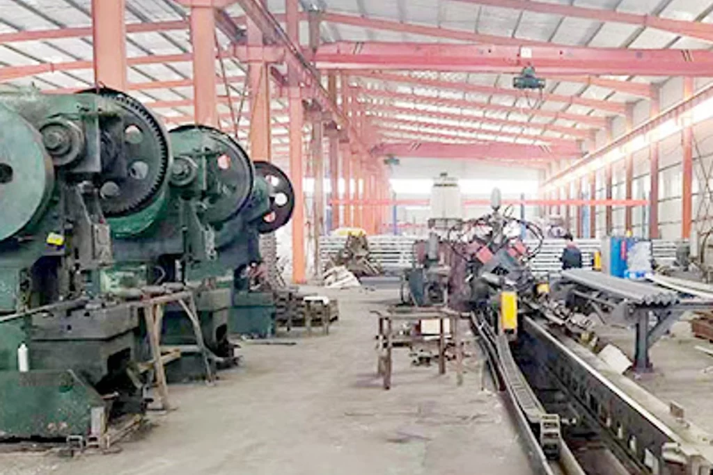
From Production to Delivery
From raw material preparation to final shipmen, every stage is caretuly controled to ensure consistent conductor quality, reliable pertormance,and sae delivery. Our roduction,
inspection, packaging, and logistics processes are managed in accordance with applicable standards and project requirements.
Production
Frames, support arms and mounting accessories are grouped by external-coil or inserted configuration. Pole bands and tower clamps remain with the corresponding mounting set.

Inspection
Inspection checks frame condition, edges, dimensions, mounting holes, model marking and the pole or tower interface. Cable-contact areas are reviewed for burrs or damage that could affect stored OPGW.
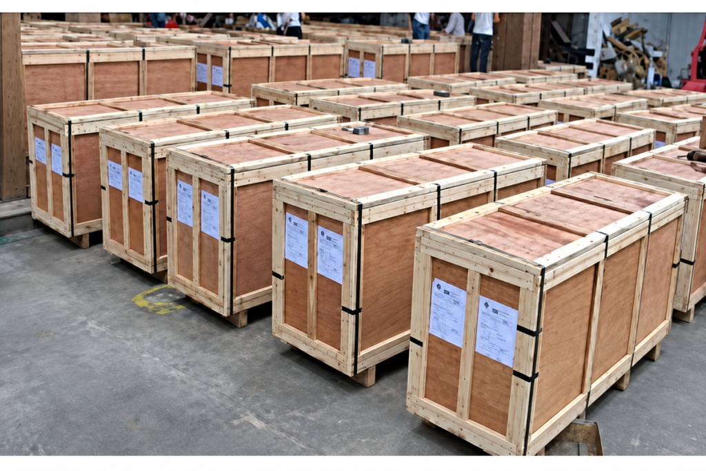
Packaging
Frames and brackets are supported against distortion, while clamps, bands and fasteners are separately packed and labelled. The component list identifies the storage arrangement and included mounting hardware.

Shipping
Packages can be grouped with the associated Downlead Clamps and Splice Closure hardware for each joint structure. Shipping marks may follow the structure number or splice-point reference to reduce site sorting.
Frequently Asked Questions
How much OPGW can the cable storage assembly hold?
Capacity depends on cable diameter, minimum bend requirement, frame geometry and the space available on the structure. We size the OPGW cable storage bracket from the reserve length and cable data instead of quoting a generic capacity that may not suit the project.
Should I choose an external-coil or inserted storage arrangement?
External storage generally provides direct access, while an inserted layout uses available internal structural space. The decision should consider tower or pole geometry, climbing access, clearances, closure position and the approved maintenance method. A structure drawing helps us recommend the suitable layout.
What is the minimum bend radius for stored OPGW?
Use the minimum bending requirement stated by the OPGW manufacturer or project specification; it is not a universal value for all cables. Send the cable data sheet and required reserve length, and we will review whether the planned storage geometry can maintain that limit.
How is the storage assembly fixed to a pole?
The available range uses pole-specific supports or stainless-steel strip selected by pole diameter. Please provide the pole material, diameter at the mounting height and any restrictions on drilling or banding so the fixing method can be defined before quotation.
Is the OPGW splice closure included with the storage assembly?
It can be quoted as a coordinated related item, but it is a separate product with its own port, fibre-capacity and sealing requirements. We will itemise storage, downlead and splice-closure components so your team can review each function and interface.
What information should I send for a complete storage layout?
Please provide cable outside diameter, reserve length, minimum bend requirement, tower or pole drawing, mounting height, closure location, downlead route and available space. We will use these details to prepare a clear assembly and mounting proposal for approval.
Request for Free Consultation
Contact Information
Send us your cable requirements and our team will respond quickly with product recommendations, technical support and quotation details.