OPGW Downlead Clamp for Towers and Poles
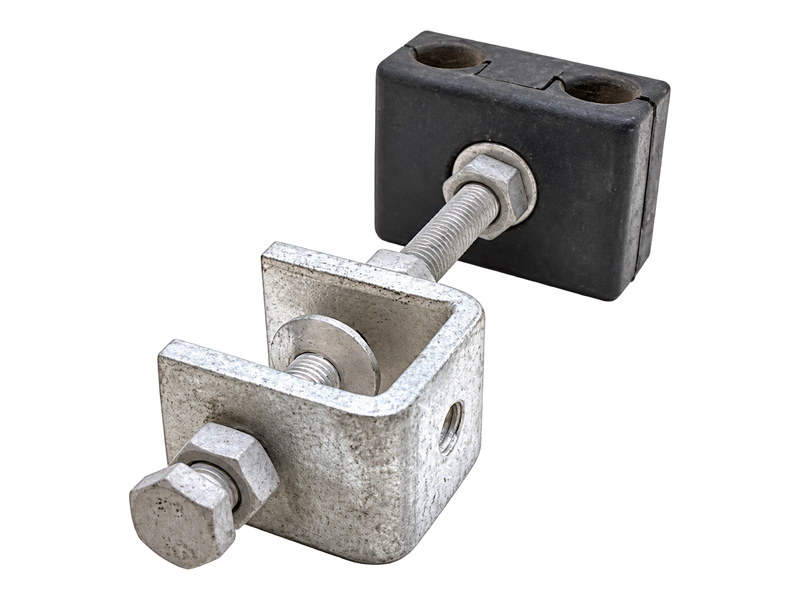
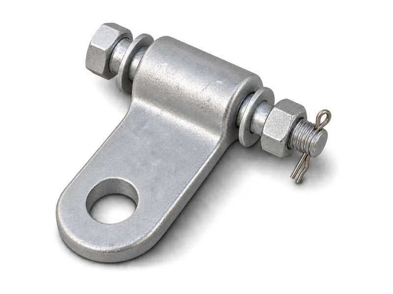
The OPGW Downlead Clamp for Towers and Poles, also known as an OPGW down lead clamp or OPGW cable guide clamp, secures optical ground wire along a structure towards the splice closure. The Downlead Clamp range covers cable diameters from 8.5 to 24.0 mm, with separate mounting arrangements for lattice towers and poles. Selection considers cable diameter, structure type, route and fixing interface so the cable remains restrained without an unsuitable local bend or clamp pressure.
Product Overview
The Downlead Clamp controls the cable path after OPGW leaves the overhead attachment area. It does not carry the span tension and cannot replace a Dead End Assembly or Suspension Assembly. Several clamps are normally positioned along the descent to limit movement, maintain the planned route and guide the cable towards the joint box. Tower and pole versions share the same cable-diameter range but use different mounting interfaces, so the structure type must be identified before quotation.
Clamp quantity and spacing cannot be determined from cable diameter alone. Structure height, changes in direction, cable stiffness, minimum bending requirement, closure position, wind exposure and the installation drawing influence the layout. For an OPGW downlead clamp for towers and poles, provide the cable outside diameter, structure dimensions, route sketch, available fixing points and splice-closure location. These details allow the optical ground wire downlead clamp, mounting accessories and route to be reviewed together. Where drilling is restricted, the proposed OPGW downlead hardware should also be checked against the available tower member or pole-banding arrangement.
Key Features
- Controlled vertical routing:The Downlead Clamp holds OPGW close to the intended structure path, reducing uncontrolled movement between the overhead attachment and splice closure.
- Tower and pole mounting options:Separate hardware interfaces suit lattice towers and poles instead of relying on one universal fixing method.
- 5–24.0 mm cable range:Listed Downlead Clamp models cover a broad outside-diameter range, while final fit remains tied to the exact cable and cable-contact detail.
- Coordinated joint-point layout:Clamp positions can be reviewed with cable storage and the joint box so the complete route maintains suitable support, bend control and maintenance access.
Product Applications
- Used for routing OPGW from tower or pole attachment points to splice locations on overhead transmission structures.
- Applied in transmission line projects, substations and optical communication infrastructure where organized cable routing is required.
- Suitable for new installations, maintenance and replacement of existing OPGW downlead systems.
Technical Specifications
| Item | Type | Available Cable Diameter (mm) | Note |
|---|---|---|---|
| Metal type Down lead clamp for tower | OTY 240A | 8.5-24.0 | for OPGW |
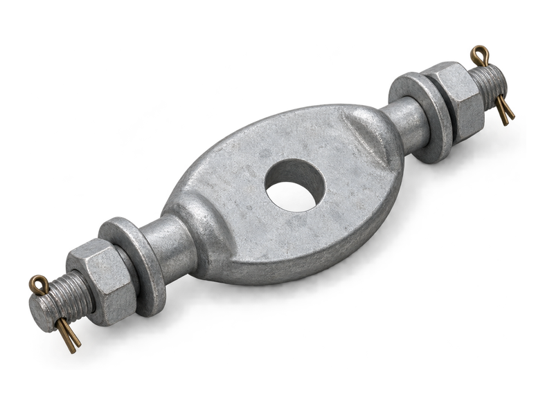
| Metal type Down lead clamp for pole | OGY 240-*** | 8.5-24.0 | For OPGW |
Request the Complete Data Sheet
From Production to Delivery
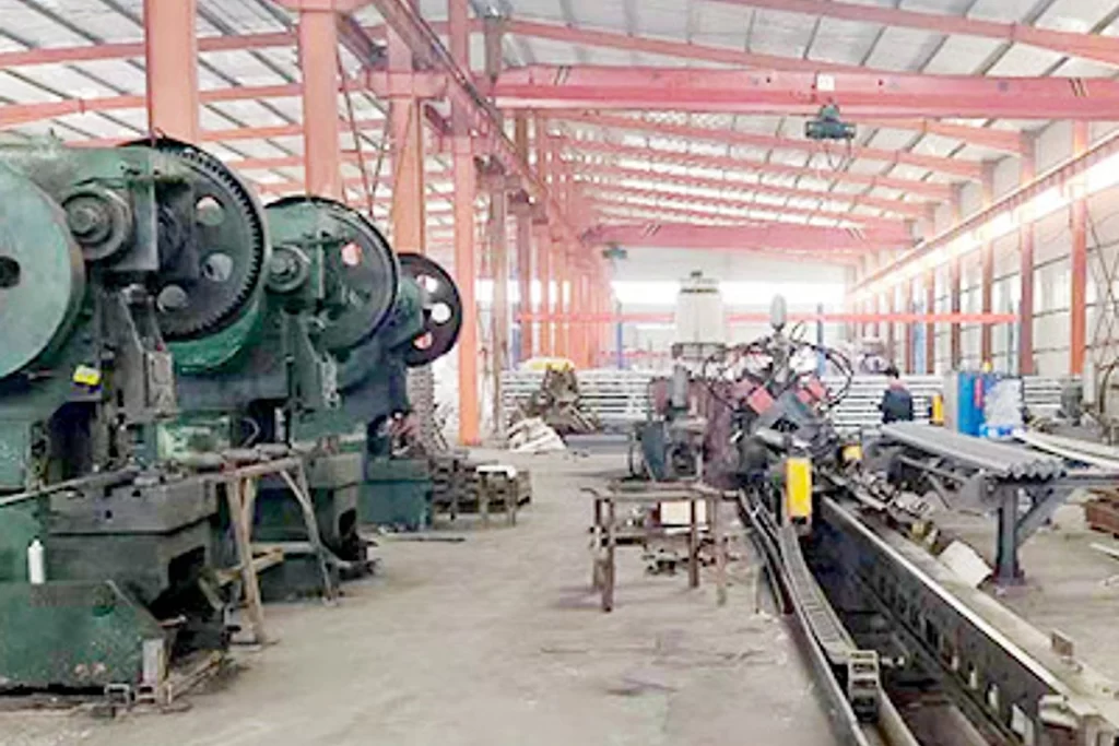
From raw material preparation to final shipmen, every stage is caretuly controled to ensure consistent conductor quality, reliable pertormance,and sae delivery. Our roduction,
inspection, packaging, and logistics processes are managed in accordance with applicable standards and project requirements.
Production
Clamp bodies, cable-contact inserts and tower- or pole-mounting parts are grouped in the correct hardware combination. Contact surfaces are kept clean and free from sharp edges during preparation.
Inspection
Inspection checks clamp surfaces, fasteners, cable-contact parts, model marking and the mounting interface. The assembled hardware is reviewed for burrs, sharp edges or mismatched components before packing.
Packaging
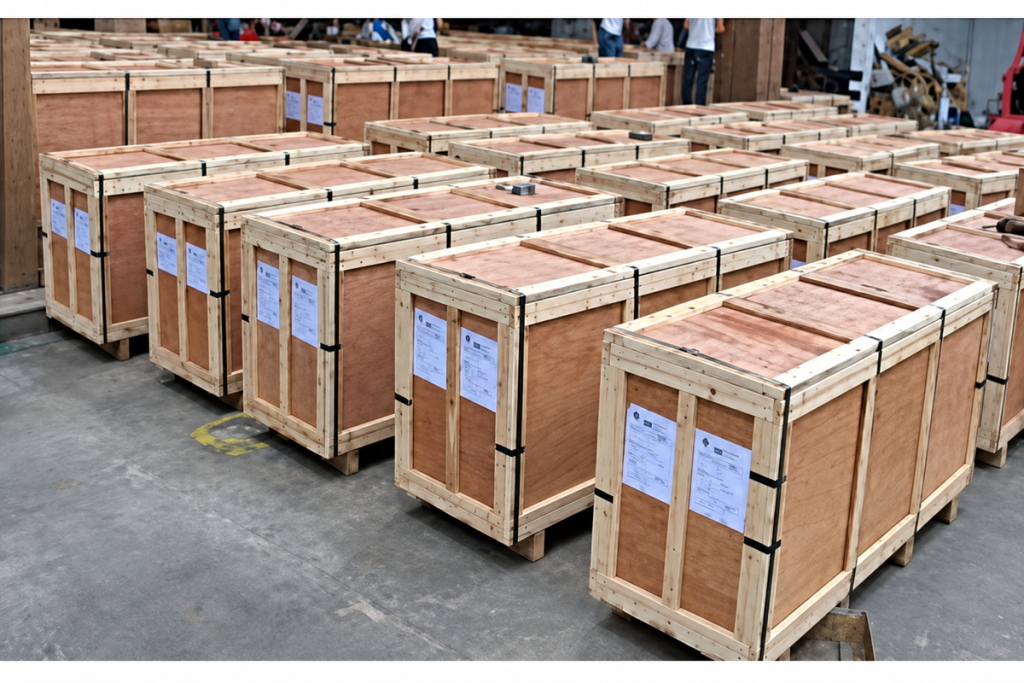
Cable-contact parts are protected from contamination and impact, while bolts, bands or adapters are bagged and labelled with their clamp sets. A component list supports site checking before work at height.
Shipping
Clamps can be grouped by tower, pole or route section so mounting variants remain separate during delivery. Shipping marks may reference the associated splice location or structure number.
Frequently Asked Questions
How many Downlead Clamps are required on one structure?
There is no safe universal quantity. The answer depends on structure height, route changes, cable behaviour, wind exposure and the installation drawing. Send the elevation and closure position; we will help prepare a clamp schedule for engineering review rather than assuming a fixed spacing.
Can the same clamp be used on both towers and poles?
The listed cable-diameter range is the same, but the mounting interface is different. Please identify the lattice-tower member or pole type and dimensions so we can propose the correct tower clamp, pole adapter or banding arrangement.
What cable information is needed for a Downlead Clamp?
Please provide the OPGW outside diameter, construction or data sheet, minimum bending requirement and the route drawing. We also need the structure type, available fixing locations and splice-closure position to check the complete path.
Can the tower clamp be installed without drilling?
A non-drilling arrangement may be possible when the tower member and available adapter are suitable. Send clear dimensions and photographs of the fixing area; we will identify the proposed mounting method for structural approval before supply.
How do you help prevent cable damage at the clamp?
We first match the clamp to the actual OPGW diameter and mounting orientation, then review the route for abrupt direction changes. Installation instructions should be followed so the cable-contact parts restrain the downlead without excessive tightening or an undersized bend.
Can Downlead Clamps be supplied with cable storage and a splice closure?
Yes, these items can be coordinated as an OPGW downlead system. Provide the reserved cable length, structure type, closure ports and mounting position; we will itemise the clamp, storage and closure scope so each interface can be checked before ordering.
Request for Free Consultation
Contact Information
Send us your cable requirements and our team will respond quickly with product recommendations, technical support and quotation details.