OPGW Preformed Dead End Assembly
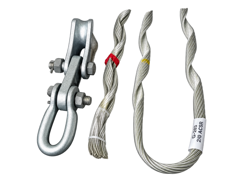
The OPGW Preformed Dead End Assembly, also known as an OPGW dead end clamp, OPGW tension clamp or OPGW dead end fitting, anchors optical ground wire at tension, angle and terminal structures. The Dead End Assembly transfers axial load through an extended preformed gripping zone. Single assemblies cover OPGW rated tensile strength groups from 60 to 160 kN, while double assemblies cover 170 to 400 kN. Selection considers cable diameter, RTS, lay direction, structure connection and grounding requirements.
Product Overview
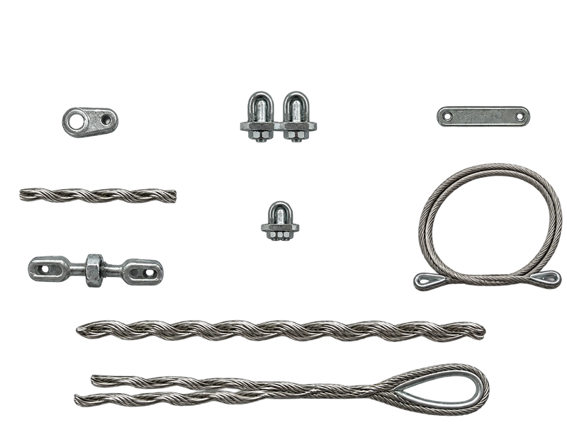
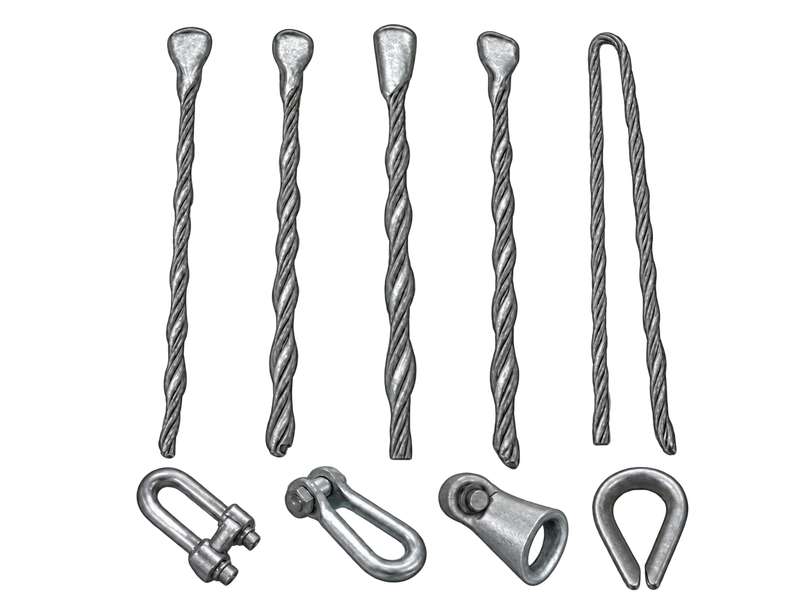
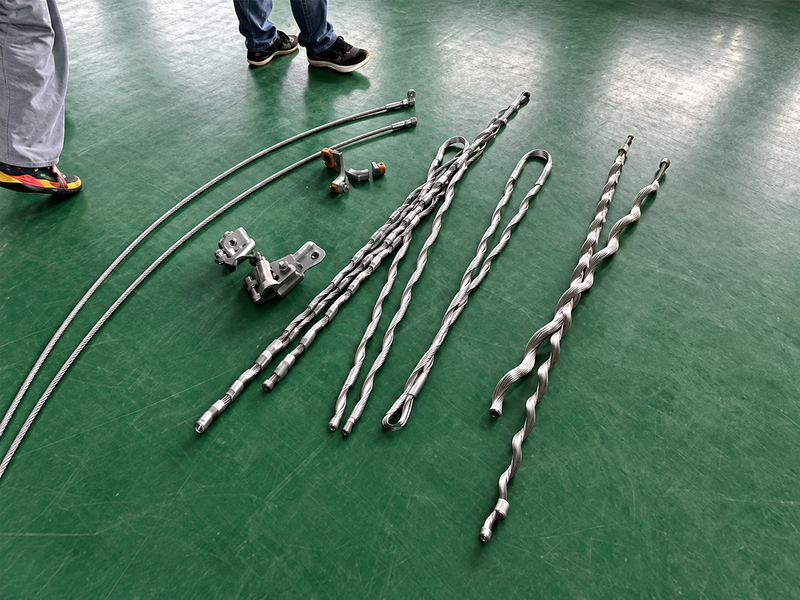
The Dead End Assembly is a mechanical termination rather than a suspension support. Helically formed rods engage a longer section of OPGW and distribute gripping pressure as axial load is transferred to the structure. Depending on the required arrangement, the complete set may include reinforcing rods, connection fittings and grounding components. Within an OPGW tension hardware system, these elements must work together without imposing an unsuitable local load on the cable or its optical core.
Single and double versions belong to different mechanical ranges and should follow the approved line design. Selection depends on the exact cable outside diameter, rated tensile strength, cable construction and lay, design load, line angle or terminal duty, attachment geometry and earthing arrangement. Matching the diameter alone is not enough because OPGW cables of similar size can have different mechanical and surface characteristics. For an enquiry, provide the cable data sheet and structure drawing so the rod set, strength class, connecting hardware and grounding scope can be reviewed as one termination system. This is especially important for replacement work, where an existing assembly code may not describe the current cable completely.
Key Features
- Extended preformed gripping zone:Helically applied rods spread axial load along a longer section of OPGW, reducing the local pressure associated with a short bolted grip and protecting the cable structure at the anchoring point.
- Single and double strength ranges:Single Dead End Assemblies cover the 60–160 kN cable RTS groups shown below, while double assemblies cover 170–400 kN groups for higher design duties and specified special conditions.
- Diameter-matched construction:Each Dead End Assembly is selected from a defined cable-diameter band so the rods engage the intended cable surface without relying on field adjustment to compensate for an incorrect size.
- Coordinated termination interface:Link fittings and grounding components can be aligned with the tower or pole arrangement, helping the mechanical termination and electrical bonding details follow the approved line design.
Product Applications
- Used at OPGW terminal towers, angle towers and strain sections where the optical ground wire is mechanically terminated.
- Applied in high-voltage overhead transmission lines, utility grid projects and power infrastructure construction requiring secureOPGW termination points.
- Suitable for new transmission line projects, line upgrades and replacement works involving existing OPGW systems.
Technical Specifications
OPGW Standard Single Preformed Tension Clamp Assembly
| Type | Available Dia.of Cable | RTS of cable (kN) | |
|---|---|---|---|
| Min. ( mm) | Max.( mm) | ||
| ONL O60/0880 | 7.6 | 8.8 | 60 |
| ONL 060/1010 | 8.9 | 10.1 | 60 |
| ONL 060/1140 | 10.2 | 11.4 | 60 |
| ONL 060/1270 | 11.5 | 12.7 | 60 |
| ONL 060/1400 | 12.8 | 14 | 60 |
| ONL 060/1530 | 14.1 | 15.3 | 60 |
| ONL 080/0880 | 7.6 | 8.8 | 80 |
| ONL 080/1010 | 8.9 | 10.1 | 80 |
| ONL 080/1140 | 10.2 | 11.4 | 80 |
| ONL O80/1270 | 11.5 | 12.7 | 80 |
| ONL 080/1400 | 12.8 | 14 | 80 |
| ONL O80/1530 | 14.1 | 15.3 | 80 |
| ONL 100/1010 | 8.9 | 10.1 | 100 |
| ONL 100/1140 | 10.2 | 11.4 | 100 |
| ONL 100/1270 | 11.5 | 12.7 | 100 |
| ONL 100/1400 | 12.8 | 14 | 100 |
| ONL 100/1530 | 14.1 | 15.3 | 100 |
| ONL 100/1660 | 15.4 | 16.6 | 100 |
| ONL 120/1140 | 10.2 | 11.4 | 120 |
| ONL 120/1270 | 11.5 | 12.7 | 120 |
| ONL 120/1400 | 12.8 | 14 | 120 |
| ONL 120/1530 | 14.1 | 15.3 | 120 |
| ONL 120/1660 | 15.4 | 16.6 | 120 |
| ONL 120/1790 | 16.7 | 17.9 | 120 |
| ONL 140/1270 | 11.5 | 12.7 | 140 |
| ONL 140/1400 | 12.8 | 14 | 140 |
| ONL140/1530 | 14.1 | 15.3 | 140 |
| ONL 140/1660 | 15.4 | 16.6 | 140 |
| ONL 140/1790 | 16.7 | 17.9 | 140 |
| ONL 140/1920 | 18 | 19.2 | 140 |
| ONL160/1400 | 12.8 | 14 | 160 |
| ONL 160/1530 | 14.1 | 15.3 | 160 |
| ONL 160/1660 | 15.4 | 16.6 | 160 |
| ONL 160/1790 | 16.7 | 17.9 | 160 |
| ONL160/1920 | 18 | 19.2 | 160 |
| ONL 160/2050 | 19.3 | 20.5 | 160 |
OPGW Extra-Strength Double Preformed Tension Clamp Assembly
| Type | Available Dia.of Cable | RTS of cable (kN) | |
|---|---|---|---|
| Min. (mm) | Max. (mm) | ||
| ONLS 170/1530 | 14.1 | 15.3 | 170 |
| ONLS 170/1660 | 15.4 | 16.6 | 170 |
| ONLS 170/1790 | 16.7 | 17.9 | 170 |
| ONLS 210/1660 | 15.4 | 16.6 | 210 |
| ONLS 210/1790 | 16.7 | 17.9 | 210 |
| ONLS 210/1920 | 18 | 19.2 | 210 |
| ONLS 250/1790 | 16.7 | 17.9 | 250 |
| ONLS 250/1920 | 18 | 19.2 | 250 |
| ONLS 250/2050 | 19.3 | 20.5 | 250 |
| ONLS 320/1920 | 18 | 19.2 | 320 |
| ONLS 320/2050 | 19.3 | 20.5 | 320 |
| ONLS 400/2050 | 19.3 | 20.5 | 400 |
| ONLS 400/2180 | 20.6 | 21.8 | 400 |
Request the Complete Data Sheet
From Production to Delivery
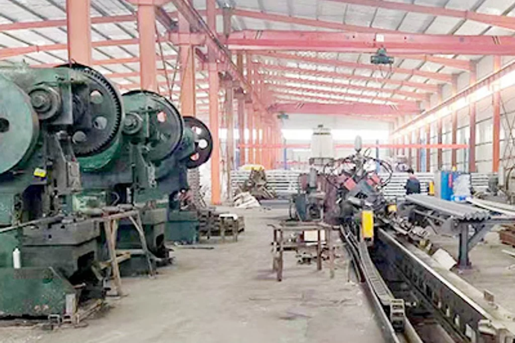
From raw material preparation to final shipmen, every stage is caretuly controled to ensure consistent conductor quality, reliable pertormance,and sae delivery. Our roduction,
inspection, packaging, and logistics processes are managed in accordance with applicable standards and project requirements.
Production
Preformed rods, reinforcement elements and connection fittings are grouped as one complete Dead End Assembly. Lay direction and component sequence remain clearly identified throughout preparation so similar-looking rod sets are not mixed.

Inspection
Inspection checks rod profile and surface condition, component count, model marking, connection fittings and any grounding parts included in the agreed assembly. Required drawings and test records are reviewed before release.
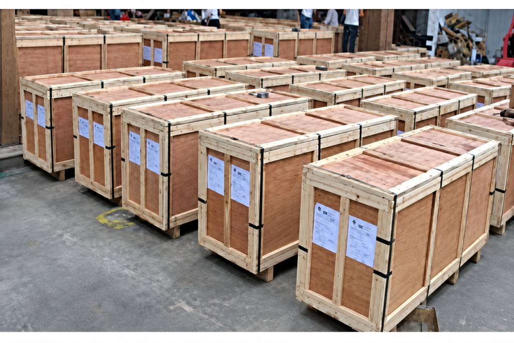
Packaging
Formed rods and metal fittings are separated and supported to prevent deformation or abrasion during handling. Each package identifies the assembly type and its included components, with installation instructions supplied in the shipment documents.

Shipping
Long formed components are supported throughout transit, and package marks can follow the customer’s tower, line-section or package-number sequence. This helps the receiving team distribute complete sets without opening every bundle.
Frequently Asked Questions
Should I specify a single or double Dead End Assembly?
Use the mechanical duty in the approved line design, not the product name alone. The available single range covers cable RTS groups from 60 to 160 kN, while the double range covers 170 to 400 kN. Send the OPGW data sheet, design load and structure drawing; we will identify the matching range and list the included components for review.
What information do you need to select a Dead End Assembly?
Please provide the cable manufacturer and designation, outside diameter, RTS, strand material and lay direction, structure type, line angle or terminal duty, design load, attachment geometry and grounding requirement. We use the complete set of details to avoid selecting rods from diameter alone.
Can an existing Dead End Assembly be replaced with another model of the same diameter?
Not automatically. Two OPGW cables with similar diameters can have different strength, surface, lay and internal optical constructions. For a replacement, we review the existing assembly record and current cable data, then identify whether a direct match is available or a revised set is required.
Are link fittings and grounding parts included with the assembly?
They can be supplied as part of the agreed assembly, but the exact scope must match the structure connection and earthing design. We will itemise rods, fittings and grounding components in the quotation so your team can see what is included and what remains by others.
Can you support approval testing or project documentation?
Yes. Tell us the governing specification, required inspection points and document list at enquiry stage. We will confirm which drawings, material records and test documents can be provided for the proposed Dead End Assembly before the order is placed.
What should be checked during installation?
Installers should verify the assembly code, cable diameter, rod lay direction, application position, connection hardware and grounding detail before applying the rods. We can provide the approved installation instruction with the shipment and clarify any project-specific component sequence before site work starts.
Request for Free Consultation
Contact Information
Send us your cable requirements and our team will respond quickly with product recommendations, technical support and quotation details.