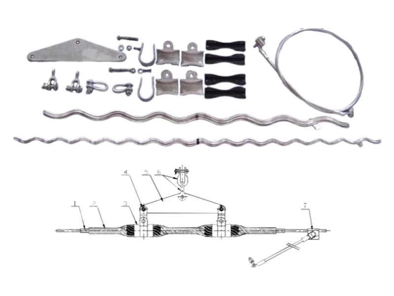
OPGW Preformed Suspension Clamp Assembly
The OPGW Preformed Suspension Clamp Assembly, also known as an OPGW suspension clamp, OPGW suspension set or OPGW suspension fitting, supports optical ground wire at tower or pole attachment points. The Suspension Assembly spreads mechanical pressure over an extended cable section through protective preformed rods and a suspension housing. Single ranges are listed by cable diameter and RTS group, while double arrangements are available where the approved line design requires two-unit support.
Product Overview
The Suspension Assembly carries the cable at a support point; it is not intended to terminate longitudinal tension. Reinforcing and outer rods form a controlled contact zone around the OPGW, while the housing transfers the suspended load to the structure. This extended interface helps limit concentrated compression and bending stress where cable movement can increase fatigue exposure. In an OPGW suspension hardware system, the rods, housing, connection fittings and attachment geometry must operate as one support arrangement.
Single and double versions serve different support layouts and must follow the line designer’s mechanical assessment. Selection considers the exact OPGW outside diameter, cable RTS, span and loading conditions, line deviation, attachment geometry and vibration-control plan. A Suspension Assembly cannot replace a Dead End Assembly where the cable must be anchored against longitudinal load. For new or replacement work, provide the cable data sheet, structure drawing and existing fitting details. We can then check the diameter band, rod arrangement, housing, connection interface and required documentation without treating similar-looking suspension sets as automatically interchangeable.
Key Features
- Distributed support pressure:Preformed rods extend the load-transfer area along the cable, reducing short-point compression and helping protect the optical ground wire at the suspension point.
- Single and double arrangements:Separate Suspension Assembly configurations allow the hardware to follow the approved structure geometry and mechanical duty rather than forcing one layout onto every line position.
- Defined diameter ranges:Each Suspension Assembly is assigned to a specific OPGW diameter band, supporting consistent rod fit and housing engagement during installation.
- Coordinated attachment system:RTS group, span duty, line deviation and vibration-control requirements can be reviewed with the OPGW suspension hardware so the support point is treated as one system.
Product Applications
- Used on tangent towers and approved suspension locations of overhead transmission lines where OPGW requires continuous mechanical support.
- Applied in utility transmission networks and high-voltage line construction projects for supporting optical ground wire between termination points.
- Suitable for new installations, maintenance and replacement projects involving existing OPGW overhead lines.
Technical Specifications
OPGW Single Suspension Clamp Assembly
| Type | Available Dia.of Cable | RTS of cable (kN) | |
|---|---|---|---|
| Min. (mm) | Max.(mm) | ||
| OCL 060/0870 | 8.1 | 8.7 | 60 |
| OCL 060/0940 | 8.8 | 9.4 | 60 |
| OCL 060/1010 | 9.5 | 10.1 | 60 |
| OCL 060/1080 | 10.2 | 10.8 | 60 |
| OCL 060/1150 | 10.9 | 11.5 | 60 |
| OCL 060/1220 | 11.6 | 12.2 | 60 |
| OCL 060/1290 | 12.3 | 12.9 | 60 |
| OCL 060/1360 | 13 | 13.6 | 60 |
| OCL O80/0870 | 8.1 | 8.7 | 80 |
| OCL 080/0940 | 8.8 | 9.4 | 80 |
| OCL 080/1010 | 9.5 | 10.1 | 80 |
| OCL 080/1080 | 10.2 | 10.8 | 80 |
| OCL 080/1150 | 10.9 | 11.5 | 80 |
| OCL 080/1220 | 11.6 | 12,2 | 80 |
| OCL 080/1290 | 123 | 12.9 | 80 |
| OCL O80/1360 | 13 | 13.6 | 80 |
| OCL 080/1430 | 13.7 | 14.3 | 80 |
| OCL100/108O | 10.2 | 10.8 | 100 |
| OCL 100/1150 | 10.9 | 11.5 | 100 |
| OCL 100/1220 | 11.6 | 12.2 | 100 |
| OCL100/1290 | 12.3 | 12.9 | 100 |
| OCL 100/1360 | 13 | 13.6 | 100 |
| OCL100/1430 | 13.7 | 14.3 | 100 |
| OCL 100/1500 | 14.4 | 15 | 100 |
| OCL100/1570 | 15.1 | 15.7 | 100 |
| OCL 120/1220 | 11.6 | 12.2 | 120 |
| OCL120/1290 | 12.3 | 12.9 | 120 |
| OCL 120/1360 | 13 | 13.6 | 120 |
| OCL 120/1430 | 13.7 | 14.3 | 120 |
| OCL 120/1500 | 14.4 | 15 | 120 |
| OCL 120/1570 | 15.1 | 15.7 | 120 |
| OCL 120/1640 | 15.8 | 16.4 | 120 |
| OCL 140/1500 | 14.4 | 15 | 140 |
| OCL 140/1570 | 15.1 | 15.7 | 140 |
| OCL140/1640 | 15.8 | 16.4 | 140 |
| OCL 140/1710 | 16.5 | 17.1 | 140 |
| OCL140/1780 | 17.2 | 17.8 | 140 |
| OCL 140/1850 | 17.9 | 18.5 | 140 |
OPGW Double Suspension Clamp Assembly
| Type | Available Dia. of Cable | |
|---|---|---|
| Min.(mm) | Max.(mm) | |
| OCLS 0940 | 8.8 | 9.4 |
| OCLS 1010 | 9.5 | 10.1 |
| OCLS 1080 | 10.2 | 10.8 |
| OCLS 1150 | 10.9 | 11.5 |
| OCLS 1220 | 11.6 | 12.2 |
| OCLS 1290 | 12.3 | 12.9 |
| OCLS 1360 | 13 | 13.6 |
| OCLS 1430 | 13.7 | 14.3 |
| OCLS 1500 | 14.4 | 15 |
| OCLS 1570 | 15.1 | 15.7 |
| OCLS 1640 | 15.8 | 16.4 |
| OCLS 1710 | 16.5 | 17.1 |
| OCLS 1780 | 17.2 | 17.8 |
| OCLS 1850 | 17.9 | 18.5 |
Request the Complete Data Sheet
From Production to Delivery
From raw material preparation to final shipmen, every stage is caretuly controled to ensure consistent conductor quality, reliable pertormance,and sae delivery. Our roduction,
inspection, packaging, and logistics processes are managed in accordance with applicable standards and project requirements.
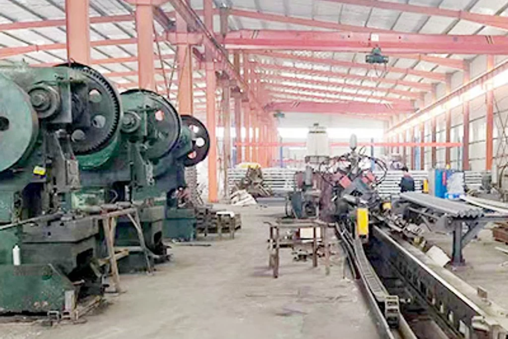
Production
Protective rods, outer rods, the suspension housing and connection fittings are grouped as one Suspension Assembly. Rod bundles remain supported and separated from metal housings during preparation and handling.
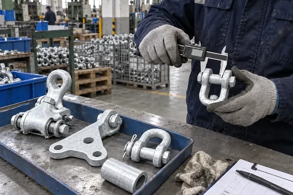
Inspection
Inspection checks rod profile and surface condition, component count, model marking, housing, fasteners and the connection interface. Any agreed strength, slip, vibration or optical-performance records are reviewed before release.
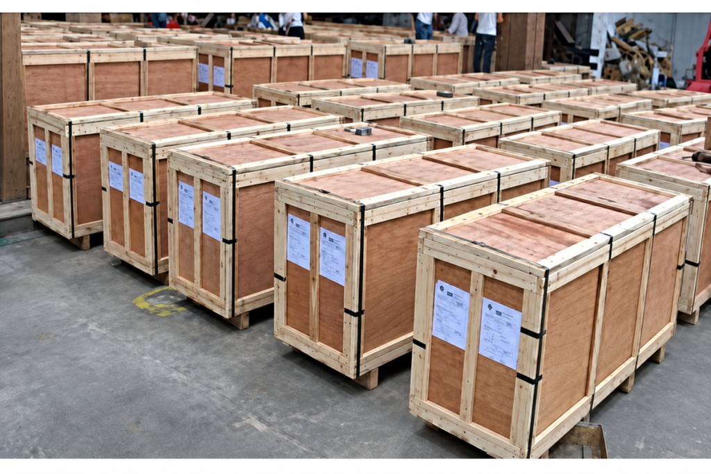
Packaging
Long rods are secured against bending and abrasion, while housings and fittings are wrapped separately to prevent metal-to-metal damage. Package labels identify the suspension arrangement and included components.

Shipping
Matched components remain together in transit, with rod bundles supported along their length. Packing lists can be arranged by tower or line section so complete Suspension Assemblies reach the intended installation points.
Frequently Asked Questions
How do I choose between a single and double Suspension Assembly?
The choice should come from the approved line geometry and mechanical design. Please send the structure drawing, line deviation, span data, cable diameter and RTS. We will identify the relevant single or double range and show the proposed component arrangement for review.
What cable data is required for Suspension Assembly selection?
We need the OPGW designation, outside diameter, RTS, construction and lay direction, together with span, tension, line angle and attachment details. This allows us to check the rods and support unit as one assembly rather than matching only the nominal diameter.
Can a Suspension Assembly be used as a dead end?
No. A Suspension Assembly supports the cable at an attachment point; a dead end is designed to transfer longitudinal tension and terminate the cable mechanically. If the structure duty is unclear, send the line profile or structure schedule and we will help separate the two hardware requirements.
Can the clamp be matched to existing tower hardware?
Usually this can be assessed from the structure drawing and clear dimensions of the existing attachment point. We will review the connection interface and list any required link fittings so your team can check clearances and orientation before ordering.
Do I still need vibration dampers with a Suspension Assembly?
Possibly. The Suspension Assembly and vibration dampers perform different functions. Damper requirement, quantity and placement depend on cable tension, span, terrain, wind exposure and line design; we can review these inputs and prepare a coordinated hardware proposal.
What documents can accompany the Suspension Assemblies?
Please state the required drawings, packing list, material records, inspection plan and test documents in the enquiry. We will confirm the available documentation for the selected assembly before order placement and keep each package traceable to its listed suspension type.
Request for Free Consultation
Contact Information
Send us your cable requirements and our team will respond quickly with product recommendations, technical support and quotation details.