PS Clevis Links

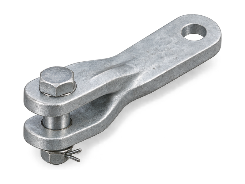
PS clevis links connect a tongue-ended fitting to a clevis-ended fitting within an overhead line insulator assembly. One end forms a fork that receives the mating tongue, while the opposite end presents a single drilled tongue for the next clevis. This end arrangement lets buyers match two different interfaces within one link. Selection depends on the fork opening, tongue thickness, tongue hole diameter, bolt designation and connection length. Table 1 lists PS-7 and PS-30 with their respective dimensions, masses and rated failure loads to support comparison of the two models.

Product Overview

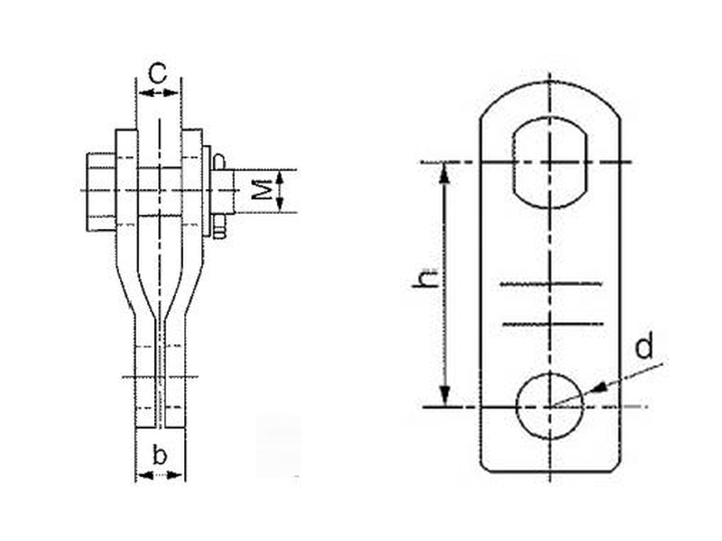
The PS body combines a receiving fork with an outgoing tongue. For these fork-to-tongue links, C describes the fork opening and M the bolt designation, while b and d describe the opposite tongue thickness and hole diameter. The h dimension sets the distance between connection centres. These separate checks match both adjoining fittings within the available space.

PS clevis links for insulator strings use a different end arrangement from P double straps, which receive tongues at both ends. The ZS series also combines a fork and a tongue, but has its own body geometry and dimensions. The main PS parts are made from hot-dip galvanised steel.

Key Features

  • Fork and tongue interfaces: The body connects a mating tongue on one side and a matching clevis on the other.
  • Separate tongue dimensions: Tongue thickness and hole diameter define the end that enters the next clevis.
  • Specified connecting length: The h dimension locates the two end connections within the assembly.
  • Model-specific load ratings: PS-7 has a rated failure load of 69 kN; PS-30 is rated at 294 kN.

Product Applications

  • Suspension string link positions: connects a tongue-ended component to an adjoining clevis-ended component in overhead conductor support hardware.
  • Tension string interface transitions: installed at the fork-to-tongue connection position between compatible fittings in a strain assembly.

Technical Specifications

Clevises (Type PS)

Clevises (Type PS)

Catalog No.Dimensions(mm)Rated Failure Load(kN)Weight(kg)
CbMdh
PS-71816162090690.6
PS-30383236391502945.9
Note:*The collar pin is stainless steel, the other parts are hot-dip galvanized steel.

Request the Complete Data Sheet

If you need a specific product catalogue or related standard file, please contact us.

From Production to Delivery

From raw material preparation to final shipmen, every stage is caretuly controled to ensure consistent conductor quality, reliable pertormance,and sae delivery. Our roduction,
inspection, packaging, and logistics processes are managed in accordance with applicable standards and project requirements.

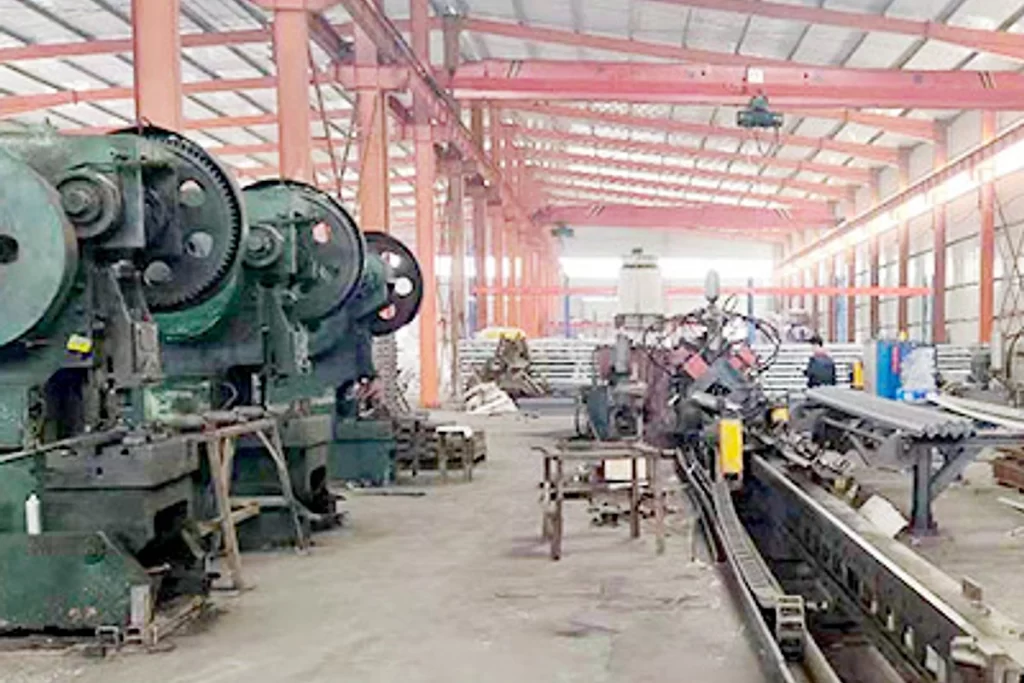
hardware production workshop

Production

The fork-to-tongue body is formed, and the fork connection and tongue hole are prepared before surface treatment and hardware assembly.

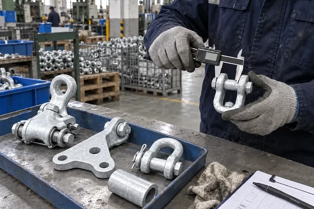
Dimensional inspection of galvanized overhead line hardware

Inspection

Dimensional inspection checks the two different interfaces, including fork opening, tongue thickness, hole diameter and centre distance. Mechanical records refer to the specified PS model and hardware.

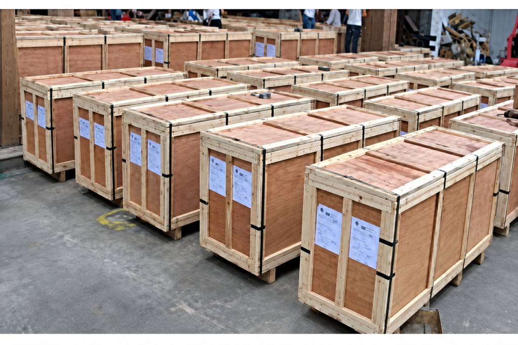
hardware packed in wooden crates for export shipment

Packaging

Packing protects the drilled tongue and fork surfaces, with the connecting hardware identified against each PS model.

Wooden crates of electrical hardware loaded for container shipment

Shipping

Dispatch documents distinguish PS-7 from PS-30 and record model quantities and the relevant technical document references.

Frequently Asked Questions

Can PS-7 meet a 70 kN failure-load requirement?

Drawing gives a rated failure load of 69 kN for PS-7, below a 70 kN requirement. PS-30 is rated at 294 kN. If the project requires a higher declared rating, the actual ordered model needs supporting technical documentation.

Both provide a fork-to-tongue connection, but PS and ZS have different body forms and dimensions. Compare C, b, d, M and h, together with body clearance and the required mechanical rating, when considering a replacement.

Provide the tongue thickness and hole details for the part entering the PS fork, plus the opening width and pin details of the clevis receiving the PS tongue. The assembly sketch should also show the required connection length and loading direction.

Identify PS-7 or PS-30, quantity, required mechanical rating and delivery destination. Include the mating tongue and clevis details, required connection length, specified bolt and retaining parts, and any project documentation requirements.

Request for Free Consultation

Contact Information

Send us your cable requirements and our team will respond quickly with product recommendations, technical support and quotation details.

Explore More

Related Products
liycy-tp-cable
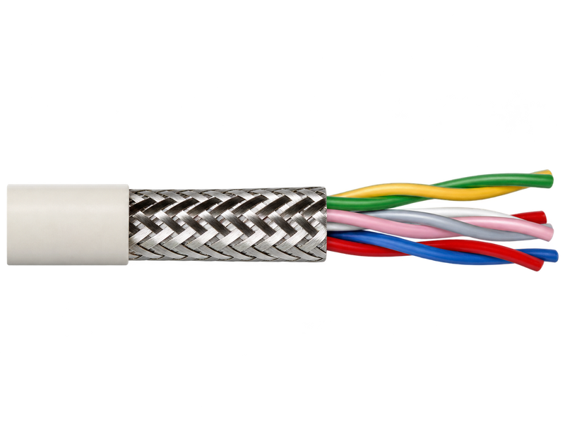
LiYCY Cable for Screened Signal and Control Wiring
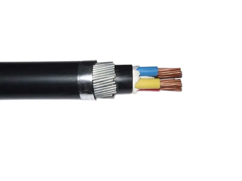
BS 6346 PVC Insulated Armoured Cable 6001000 V
BS 5467 XLPE Insulated Armoured Power Cable
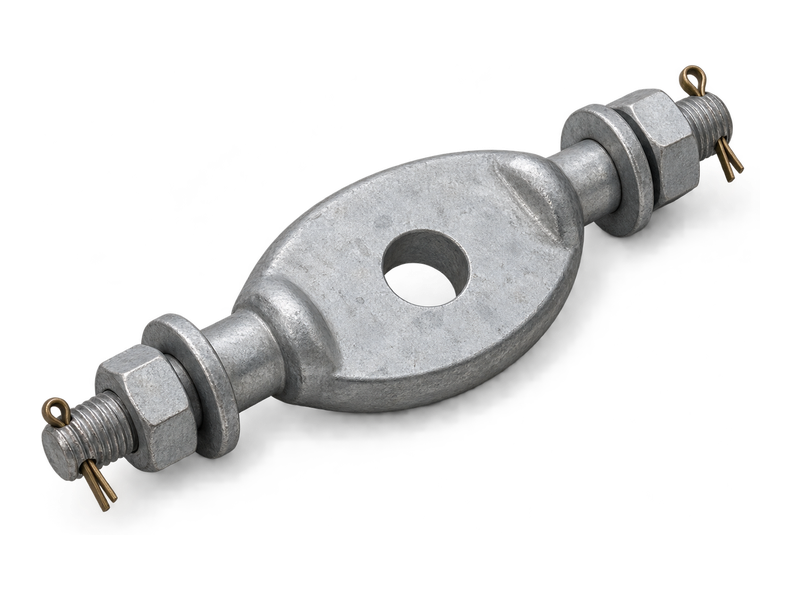
GD link fitting with central eye and transverse bolted connections for overhead line hardware
Twisted Link Plates — Type GD
Compatible Hardware
liycy-tp-cable
LiYCY Cable for Screened Signal and Control Wiring
BS 6346 PVC Insulated Armoured Cable 6001000 V
BS 5467 XLPE Insulated Armoured Power Cable
GD link fitting with central eye and transverse bolted connections for overhead line hardware
Twisted Link Plates — Type GD
Knowledge Articles
AAC vs AAAC vs ACSR: Which Overhead Conductor to Choose?
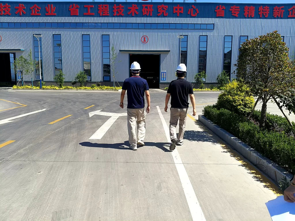
Customer Visits Our Factory for Product Inspection and Quality Verification
AAAC all aluminium alloy conductor stranded wire
AAAC Conductor Selection Guide: How to Choose the Right AAAC for Overhead Lines

For Immediate Assistance, Please Contact us Now!