TACSR/TACSR-AW Thermal-Resistant Conductor
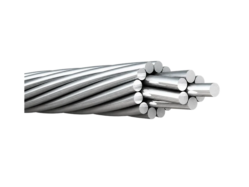
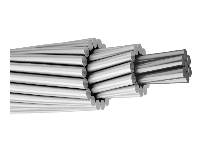
TACSR conductor replaces the hard-drawn aluminium of conventional ACSR with thermal-resistant aluminium-alloy outer wires while retaining steel reinforcement. TACSR-AW uses an aluminium-clad steel core instead of the conventional coated-steel option. It provides an ACSR-type route to higher-temperature operation without a gap or Invar core.
Key Advantages
- Thermal-resistant current path: TAL outer wires are selected for elevated-temperature duty.
- Familiar reinforced geometry: Round alloy strands are arranged around a steel core.
- Core choice available: Conventional coated steel and aluminium-clad steel serve different specifications.
Product Overview
The principal technical change from ACSR to TACSR is the outer aluminium material. Thermal-resistant aluminium alloy is used to retain specified properties under elevated-temperature conditions, while the central core continues to provide reinforcement and influence strength and sag-tension behaviour. TACSR is therefore different from gap-type and Invar-core HTLS systems.
TACSR and TACSR-AW require separate core data. Core material and conductivity grade affect resistance, mass, strength, corrosion interfaces and compression fittings. A thermal rating must also use stated weather, surface and temperature assumptions and be checked against conductor, hardware and clearance limits.
Key Features
- Thermal-resistant aluminium-alloy outer wires replace conventional hard-drawn aluminium.
- A steel reinforcing core retains the composite load-sharing logic of a round-wire reinforced conductor.
- TACSR-AW introduces an aluminium-clad steel core and requires its own construction and fitting data.
- Allowable temperature and current are project outputs based on approved material, hardware and line conditions.
Product Applications
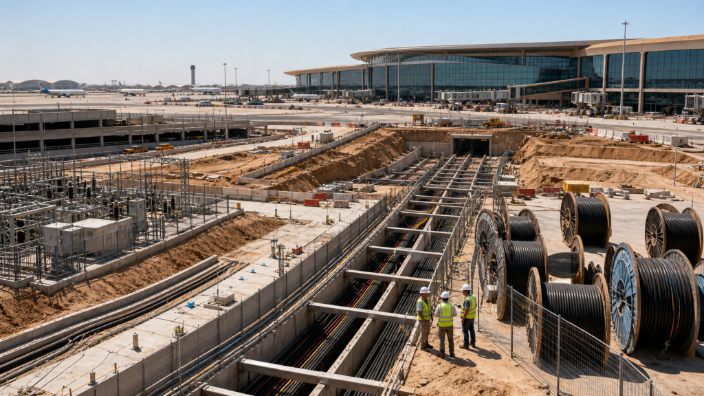
- Overhead transmission and distribution requiring higher thermal capacity than a conventional design
- Existing-corridor uprating where a round-wire steel-reinforced construction is preferred
- Routes comparing conventional coated-steel and aluminium-clad steel core systems
Technical Specifications
TACSR LS Cable & System Standard (60% IACS)
| Conductor Size (mm2) | Stranding (Nos./mm) | Min. Breaking Load (kgf) | Reference | |||||||||||||
|---|---|---|---|---|---|---|---|---|---|---|---|---|---|---|---|---|
| Cross-sectional Area (mm2) | Overall Diameter (mm) | Weight (kg/km) | DC Resistance at 20℃ (Ω/km) | Modulus of Elasticity (kgf/mm2) | Coefficient of Linear Expansion (10-6/℃) | Standard Length (m) | Current Carrying Capacity (A) | |||||||||
| TAl | ST | TAl | ST | Total | TAl | ST | TAl | ST | Total | |||||||
| 58 | 6/3.5 | 1/3.5 | 1,980 | 57.73 | 9.621 | 67.35 | 10.5 | 3.5 | 158.1 | 75.04 | 233.1 | 0.505 | 8,400 | 18.9 | 1,000 | 343 |
| 80 | 6/4.2 | 1/4.2 | 2,770 | 83.10 | 13.85 | 96.95 | 12.6 | 4.2 | 227.5 | 108.0 | 335.5 | 0.350 | 8,400 | 18.9 | 1,000 | 430 |
| 95 | 6/4.5 | 1/4.5 | 3,810 | 95.40 | 15.90 | 111.3 | 13.5 | 4.5 | 261.2 | 124.0 | 385.2 | 0.306 | 8,400 | 18.9 | 1,000 | 478 |
| 80 | 15/2.6 | 4/2.6 | 4,720 | 79.64 | 21.24 | 100.9 | 13.0 | 7.8 | 219.2 | 166.5 | 385.7 | 0.368 | 9,390 | 17.6 | 2,000 | 448 |
| 100 | 15/2.9 | 4/2.9 | 5,580 | 99.08 | 26.42 | 125.5 | 14.5 | 8.7 | 272.8 | 207.1 | 479.9 | 0.296 | 9,390 | 17.6 | 2,000 | 517 |
| 120 | 15/3.2 | 4/3.2 | 5,550 | 120.6 | 32.17 | 152.8 | 16.0 | 9.6 | 332.2 | 252.2 | 584.4 | 0.243 | 9,390 | 17.6 | 2,000 | 590 |
| 120 | 30/2.3 | 7/2.3 | 5,540 | 124.7 | 29.09 | 153.8 | 16.1 | 6.9 | 345.7 | 228.0 | 573.7 | 0.237 | 9,080 | 18.0 | 2,000 | 598 |
| 160 | 30/2.6 | 7/2.6 | 6,980 | 159.3 | 37.16 | 196.5 | 18.2 | 7.8 | 441.5 | 291.3 | 732.8 | 0.185 | 9,080 | 18.0 | 2,000 | 706 |
| 200 | 30/2.9 | 7/2.9 | 8,640 | 198.2 | 46.24 | 244.4 | 20.3 | 8.7 | 549.3 | 362.4 | 911.7 | 0.149 | 9,080 | 18.0 | 2,000 | 816 |
| 240 | 30/3.2 | 7/3.2 | 10,210 | 241.3 | 56.29 | 297.6 | 22.4 | 9.6 | 668.9 | 441.3 | 1,110 | 0.122 | 9,080 | 18.0 | 2,000 | 932 |
| 330 | 26/4.0 | 7/3.1 | 10,950 | 326.8 | 52.84 | 379.6 | 25.3 | 9.3 | 905.4 | 414.2 | 1,320 | 0.0904 | 8,360 | 19.0 | 2,000 | 1,128 |
| 410 | 26/4.5 | 7/3.5 | 13,910 | 413.4 | 67.35 | 480.8 | 28.5 | 10.5 | 1,145 | 527.9 | 1,673 | 0.0714 | 8,360 | 19.0 | 2,000 | 1,322 |
| 480 | 45/3.7 | 7/2.47 | 11,260 | 483.8 | 33.54 | 517.34 | 29.6 | 7.41 | 1336.1 | 262.9 | 1,599 | 0.0610 | 7,250 | 20.8 | 2,000 | 1,425 |
| 520 | 54/3.5 | 7/3.5 | 15,600 | 519.5 | 67.35 | 586.9 | 31.5 | 10.5 | 1,441 | 527.9 | 1,969 | 0.0569 | 7,990 | 19.5 | 1,600 | 1,504 |
| 610 | 54/3.8 | 7/3.8 | 18,350 | 612.4 | 79.38 | 691.8 | 34.2 | 11.4 | 1,698 | 622.2 | 2,320 | 0.0481 | 7,990 | 19.5 | 1,600 | 1,682 |
| 680 | 54/4.0 | 7/4.0 | 19,810 | 678.8 | 87.99 | 766.8 | 36.0 | 12.0 | 1,882 | 689.8 | 2,572 | 0.0436 | 7,990 | 19.5 | 1,600 | 1,797 |
| 680 | 45/4.4 | 7/2.9 | 15,580 | 684.5 | 46.24 | 730.7 | 35.1 | 8.7 | 1,898 | 362.4 | 2,260 | 0.0431 | 7,250 | 20.8 | 1,600 | 1,787 |
| 810 | 45/4.8 | 7/3.2 | 18,480 | 814.5 | 56.29 | 870.8 | 38.4 | 9.6 | 2,259 | 441.3 | 2,700 | 0.0363 | 7,250 | 20.8 | 1,600 | 2,004 |
| 1,160 | 84/4.2 | 7/4.2 | 27,830 | 1.163 | 96.95 | 1,260 | 46.2 | 12.6 | 3,236 | 759.8 | 3,996 | 0.0254 | 7,430 | 20.5 | 1,200 | 2,573 |
| 1,520 | 84/4.8 | 7/4.8 | 36,390 | 1.520 | 126.7 | 1,647 | 52.8 | 14.4 | 4,228 | 993.3 | 5,222 | 0.0195 | 7,430 | 20.5 | 1,200 | 3,035 |
TACSR/AW — 20.3% Conductivity AW
| Conductor Size (mm2) | Stranding (Nos./mm) | Min. Breaking Load (kgf) | Reference | ||||||||||
|---|---|---|---|---|---|---|---|---|---|---|---|---|---|
| Cross-sectional Area (mm2) | Overall Diameter (mm) | Weight (kg/km) | DC Resistance at 20℃ (Ω/km) | Modulus of Elasticity (kgf/mm2) | Coefficient of Linear Expansion (10-6/℃) | Standard Length (m) | Current Carrying Capacity (A) | ||||||
| TAl | AW | TAl | AW | TAl | AW | ||||||||
| 120 | 30/2.3 | 7/2.3 | 5,540 | 124.7 | 29.08 | 16.1 | 6.9 | 536.5 | 0.219 | 8,100 | 19.2 | 2,000 | 624 |
| 160 | 30/2.6 | 7/2.6 | 6,980 | 159.3 | 37.16 | 18.2 | 7.8 | 685.4 | 0.171 | 8,100 | 19.2 | 2,000 | 734 |
| 200 | 30/2.9 | 7/2.9 | 8,640 | 198.2 | 46.24 | 20.3 | 8.7 | 852.8 | 0.138 | 8,100 | 19.2 | 2,000 | 847 |
| 210 | 30/3.2 | 7/3.2 | 10,160 | 241.3 | 56.29 | 22.4 | 9.6 | 1,038 | 0.113 | 8,100 | 19.2 | 2,000 | 968 |
| 330 | 26/4.0 | 7/3.1 | 11,200 | 326.8 | 52.84 | 25.3 | 9.3 | 1,252 | 0.0856 | 7,620 | 20.0 | 2,000 | 1,159 |
| 410 | 26/4.5 | 7/3.5 | 14,230 | 413.4 | 67.35 | 28.5 | 10.5 | 1,587 | 0.0676 | 7,630 | 20.0 | 2,000 | 1,358 |
| 480 | 45/3.7 | 7/2.47 | 11,260 | 483.84 | 33.54 | 29.6 | 7.4 | 1,561 | 0.0595 | 6,910 | 21.5 | 2,000 | 1,437 |
| 520 | 54/3.5 | 7/3.5 | 15,920 | 519.5 | 67.35 | 31.5 | 10.5 | 1,883 | 0.0544 | 7,390 | 20.4 | 1,600 | 1,537 |
| 610 | 54/3.8 | 7/3.8 | 18,730 | 612.4 | 79.38 | 34.2 | 11.4 | 2,219 | 0.0461 | 7,330 | 20.4 | 1,600 | 1,717 |
| 680 | 45/4.4 | 7/2.9 | 15,580 | 684.5 | 46.24 | 35.1 | 8.7 | 2,201 | 0.0422 | 6,900 | 21.5 | 1,600 | 1,805 |
| 810 | 45/4.8 | 7/3.2 | 18,730 | 814.5 | 56.29 | 38.4 | 9.6 | 2,628 | 0.0354 | 6,910 | 21.5 | 1,600 | 2,028 |
| 950 | 84/3.8 | 7/3.8 | 23,780 | 952.6 | 79.38 | 41.8 | 11.4 | 3,170 | 0.0302 | 7,030 | 21.2 | 1,200 | 2,292 |
| 1,160 | 84/4.2 | 7/4.2 | 28,720 | 1,163 | 96.95 | 46.2 | 12.6 | 3,872 | 0.0247 | 7,030 | 21.2 | 1,200 | 2,606 |
| 1,520 | 84/4.8 | 7/4.8 | 37,520 | 1,520 | 126.7 | 52.8 | 14.4 | 5,060 | 0.0189 | 7,030 | 21.2 | 1,200 | 3,075 |
TACSR/AW — 23% Conductivity AW
| Conductor Size (mm2) | Stranding (Nos./mm) | Min. Breaking Load (kgf) | Reference | ||||||||||
|---|---|---|---|---|---|---|---|---|---|---|---|---|---|
| Cross-Sectional Area (mm2) | Overall Diameter (mm) | Weight (kg/km) | DC Resistance at 20 ( /km) | Modulus of Elasticity (kgf/mm2) | Coefficient of Linear Expansion (10-6/ ) | Standard Length (m) | Current Carrying Capacity (A) | ||||||
| TAL | AW | TAL | AW | TAL | AW | ||||||||
| 120 | 30/2.3 | 7/2.3 | 5,410 | 124.7 | 29.08 | 16.1 | 6.9 | 528.9 | 0.217 | 7,980 | 19.4 | 2,000 | 625 |
| 160 | 30/2.6 | 7/2.6 | 6,810 | 159.3 | 37.16 | 18.2 | 7.8 | 675.7 | 0.170 | 7,980 | 19.4 | 2,000 | 736 |
| 200 | 30/2.9 | 7/2.9 | 8,440 | 198.2 | 46.24 | 20.3 | 8.7 | 840.7 | 0.136 | 7,980 | 19.4 | 2,000 | 854 |
| 210 | 30/3.2 | 7/3.2 | 10,210 | 241.3 | 56.29 | 22.4 | 9.6 | 1,024 | 0.112 | 7,980 | 19.4 | 2,000 | 973 |
| 330 | 26/4.0 | 7/3.1 | 10,950 | 326.8 | 52.84 | 25.3 | 9.3 | 1,238 | 0.085 | 7,540 | 20.2 | 2,000 | 1,163 |
| 410 | 26/4.5 | 7/3.5 | 13,910 | 413.4 | 67.35 | 28.5 | 10.5 | 1,570 | 0.0671 | 7,550 | 20.2 | 2,000 | 1,363 |
| 480 | 45/3.7 | 7/2.47 | 11,110 | 483.84 | 33.54 | 29.6 | 7.4 | 1,550 | 0.0592 | 6,880 | 20.6 | 2,000 | 1,441 |
| 520 | 54/3.5 | 7/3.5 | 15,600 | 519.5 | 67.35 | 31.5 | 10.5 | 1,865 | 0.0541 | 7,330 | 20.6 | 1,600 | 1,541 |
| 610 | 54/3.8 | 7/3.8 | 18,350 | 612.4 | 79.38 | 34.2 | 11.4 | 2,198 | 0.0458 | 7,320 | 20.6 | 1,600 | 1,722 |
| 680 | 45/4.4 | 7/2.9 | 15,600 | 684.5 | 46.24 | 35.1 | 8.7 | 2,189 | 0.0420 | 6,860 | 21.6 | 1,600 | 1,809 |
| 810 | 45/4.8 | 7/3.2 | 18,480 | 814.5 | 56.29 | 38.4 | 9.6 | 2,613 | 0.0353 | 6,880 | 21.6 | 1,600 | 2,031 |
| 950 | 84/3.8 | 7/3.8 | 23,100 | 952.6 | 79.38 | 41.8 | 11.4 | 3,149 | 0.0300 | 6,980 | 21.3 | 1,200 | 2,299 |
| 1,160 | 84/4.2 | 7/4.2 | 28,270 | 1,163 | 96.95 | 46.2 | 12.6 | 3,847 | 0.0246 | 6,980 | 21.3 | 1,200 | 2,611 |
| 1,520 | 84/4.8 | 7/4.8 | 36,960 | 1,520 | 126.7 | 52.8 | 14.4 | 5,027 | 0.0189 | 6,980 | 21.3 | 1,200 | 3,075 |
Request the Complete Data Sheet
From Production to Delivery
From raw material preparation to final shipmen, every stage is caretuly controled to ensure consistent conductor quality, reliable pertormance,and sae delivery. Our roduction,
inspection, packaging, and logistics processes are managed in accordance with applicable standards and project requirements.
Production
TAL wire is produced to the approved thermal-resistant condition, and the selected zinc-coated or aluminium-clad steel core is prepared before concentric stranding.

Inspection
Inspection verifies TAL material identification, core type, wire dimensions, strand arrangement, finished diameter, strength and the selected catalogue table.
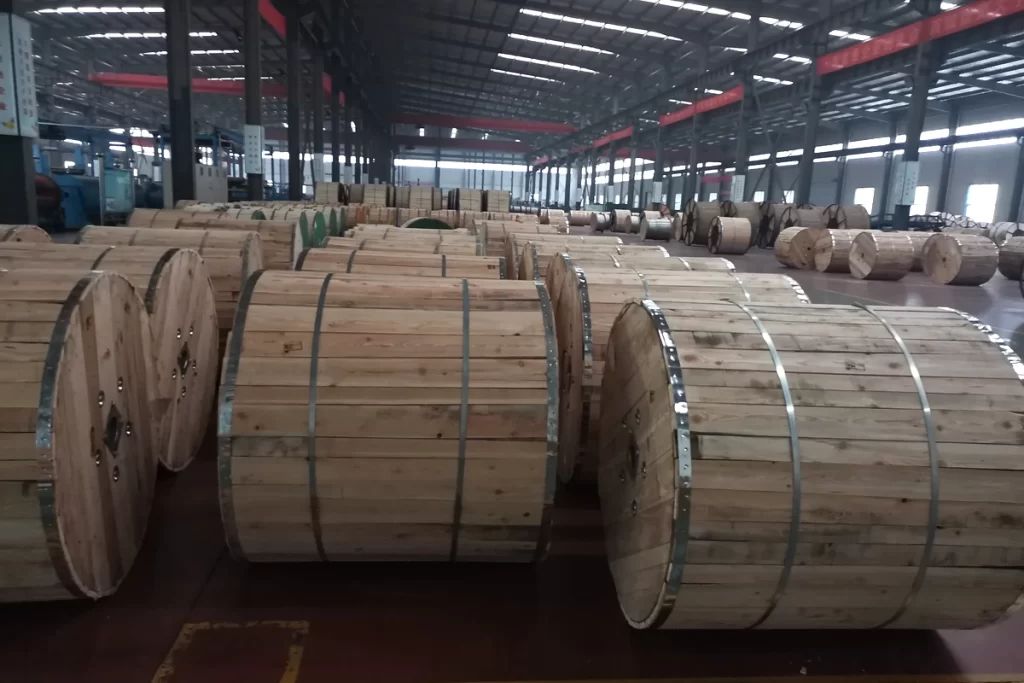
Packaging
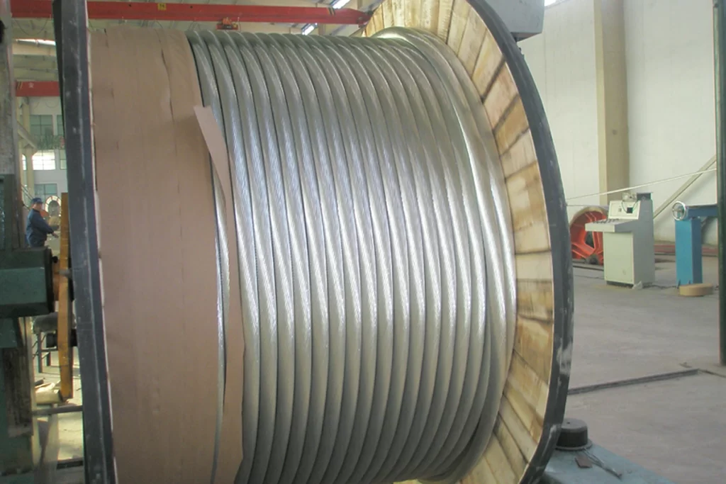
Packaging uses controlled winding and core protection to prevent strand damage, core displacement or surface contamination before installation.
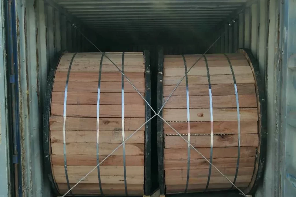
Shipping
Shipment documents distinguish TACSR from each TACSR-AW conductivity-grade table and identify the matching test and hardware records.
Frequently Asked Questions
What changes when conventional ACSR is replaced by TACSR?
We provide a wide range of cable materials and electrical products, including aluminum conductors, aluminum rods, aluminum wires, overhead conductors, medium and low voltage power cables, cable insulation materials, filling materials, shielding materials, and cable manufacturing consumables.We provide customized solutions according to different cable manufacturing requirements.
Does TACSR require the specialised stringing method used for gap conductors?
xxxxxxxxxxxxxxxxxxxxxxxxxxxxxxxxxxxxxxxxxxxxxxxxxxxxxxx
When should TACSR-AW be specified?
Specify TACSR-AW when aluminium-clad steel is required for the core material system. Its conductivity grade, core construction and mechanical rating must be included in the approved data sheet.
Can a catalogue current value be used as the TACSR line rating?
No. Line rating depends on conductor and ambient temperature, wind, solar input, surface properties, altitude, clearances and operating policy. Use a project calculation with stated assumptions.
Which existing ACSR items need checking during a TACSR uprating?
Check structures, clearances, insulator strings, clamps, joints, dead-ends, dampers, spacers, jumpers, stringing equipment and protection settings against the new diameter, temperature, current and loads.
What should be included in a TACSR thermal and mechanical review?
Provide conductor construction, core option, material data, spans, tensions, weather loads, temperature range, target current, creep and sag assumptions, clearances, hardware and installation conditions.
Request for Free Consultation
Contact Information
Send us your cable requirements and our team will respond quickly with product recommendations, technical support and quotation details.