Three Core Medium Voltage Power Cable to IEC 60502-2
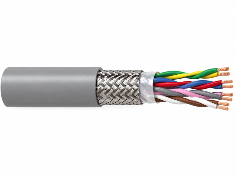
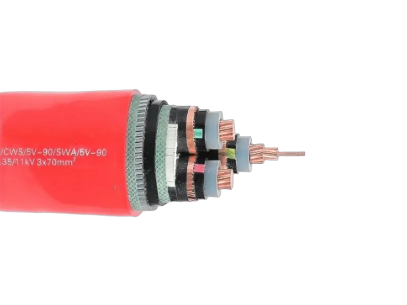
Engineered for medium voltage power distribution across a wide voltage range from 1.8/3kV up to 26/35kV at 50Hz, this three core cable features triple-extruded conductor and insulation screens for reliable electrical performance. Manufactured to IEC 60502 Part 1 and Part 2 standards, it offers versatile installation options — from power stations and indoor cable ducts to outdoor, underground, underwater and cable tray applications in industrial facilities and switchboards.
Key Advantages
XLPE / EPR / HEPR Insulation
Metallic Screen
Three Core Design
IEC 60502 Part 2(3.6/6KV to 18/30KV)
Construction
| Conductor | Plain annealed copper or aluminum complying with IEC 60228 class 1 or 2. |
| Insulation | Insulation is of polyvinyl chloride (PVC) intended for 1.8/3.6 kV and 3.6/6 kV Power Cable, cross-linked polyethylene compound (XLPE) or ethylene propylene rubber (EPR/HEPR). |
| Conductor Screen | The conductor screen consists of an extruded layer of nonmetallic, semi-conducting compound applied on top of a semi-conducting tape. The conductor screen is applied under triple extrusion process over the conductor along with the insulation and the insulation screen. The extruded semi-conducting compound is firmly bonded to the insulation to exclude all air voids and can be easily hand stripped on site. The conductor screen is not necessary for both PVC and EPR/HEPR insulated 1.8/3.6kV and 3.6/6kV Power Cable. |
| Insulation Screen | The insulation screen consists of an extruded layer of nonmetallic, semi-conducting compound extruded over the insulation of each core. The extruded semi-conducting layer shall consist of bonded or cold strippable semi-conducting compound capable of removal for jointing or terminating. As an option, a semi-conducting tape may be applied over the individual cores or core assembly as a bedding for the metallic layer. The minimum thickness is 0.3 mm and the maximum resistivity is 500 Ohm-m at 90°C. The screen is tightly fitted to the insulation to exclude all air voids and can be easily hand stripped on site. The insulation screen is not necessary for both PVC and EPR/HEPR insulated 1.8/3.6kV and 3.6/6kV Power Cable. The screen may be covered by semi-conductive water blocking swellable tape to ensure longitudinal watertightness. |
| Metallic Layer | The metallic layer may be applied over the individual cores or the core assembly collectively.The following types of metallic layers are provided:1) Metallic Screen2) Concentric Conductor3) Metallic Sheath4) Metallic Armor |
| Inner Covering & Fillers | For Power Cable with a collective metallic layer or Power Cable with a metallic layer over each individual core with additional collective metallic layers, semi-conducting inner covering and fillers shall be applied over the laid-up cores. The inner covering and fillers are made of nonhygroscopic material like polypropylene, except if the cable is to be made longitudinally watertight. The inner covering is extruded in general, but may be lapped if the interstices between the cores are filled. The approximate thickness of extruded inner coverings is given. |
| Separation Sheath (for armored cable) | The separation sheath comprises a layer of extruded PVC, PE or LSZH applied over the laid up cores under the armor. PVC is normally of grade ST2 and PE of grade ST7. The nominal thickness is calculated by 0.02Du + 0.6mm where Du is the fictitious diameter under the sheath in mm. For Power Cable without a lead sheath, the nominal separation sheath thickness shall not be less than 1.2mm. For Power Cable where the separation sheath is applied over the lead sheath, the nominal separation sheath thickness shall not be less than 1.0mm. |
| Lapped Bedding (for armored lead sheathed cable) | The lapped bedding applied to the lead sheath consists of either impregnated/synthetic compounded paper tapes or a combination of two layers of these paper tapes followed by a few layers of compounded fabulous materials. The thickness is around 1.5mm. |
| Armour (for armored cable) | The armor is applied over the inner covering helically. It consists of either flat galvanized steel wire armor (strip), round galvanized steel wire armor, or double steel tape armor. The armor up to and including 15mm, flat wire armor will not be used. The tape armor is applied helically in two layers so that the outer tape is approximately central over the gap of the inner tape. If tape armor is used, the inner covering shall be reinforced by taped bedding. |
| Over Sheath | Overall sheath comprises a layer of extruded either thermoplastic compound (PVC ST3 type or PE ST7 type or LSZH) or elastomeric compound (polychlorprene CSP or chlorosulfonated PE). The nominal over sheath thickness is calculated by 0.035D+1 where D is the fictitious diameter immediately under the over sheath in mm. For unarmored Power Cable and Power Cable with the over sheath not applied over the armor, metallic screen or concentric conductor, the nominal over sheath thickness shall not be less than 1.4mm. And for Power Cable with over sheath applied over the armor, metallic screen or concentric conductor, the nominal over sheath thickness shall not be less than 1.8mm. |
Parameters
| Nom. Cross-Section Area | Nom. Insulation Thickness | Copper Wire Screen Area | Unarmoured Cables | Steel Round-Wire Armoured Cables | |||||||
|---|---|---|---|---|---|---|---|---|---|---|---|
| Nom. Sheath Thickness | Approx. Overall Diameter | Approx. Weight | Nom. Bedding Thickness | Armour Wire Size | Nom. Sheath Thickness | Approx. Weight | |||||
| CU | AL | CU | AL | ||||||||
| mm² | mm | mm² | mm | mm | kg/km | mm | mm | mm | kg/km | ||
| 10 | 2.5 | 16 | 2 | 30 | 980 | 790 | 1.2 | 2 | 2.1 | 2310 | 2120 |
| 16 | 2.5 | 16 | 2 | 31 | 1190 | 890 | 1.2 | 2 | 2.2 | 2600 | 2290 |
| 25 | 2.5 | 16 | 2.1 | 34 | 1560 | 1080 | 1.2 | 2 | 2.3 | 3080 | 2600 |
| 35 | 2.5 | 16 | 2.2 | 37 | 1930 | 1270 | 1.3 | 2.5 | 2.4 | 3950 | 3280 |
| 50 | 2.5 | 16 | 2.3 | 40 | 2370 | 1480 | 1.3 | 2.5 | 2.5 | 4530 | 3630 |
| 70 | 2.5 | 16 | 2.4 | 43 | 3110 | 1820 | 1.4 | 2.5 | 2.6 | 5510 | 4210 |
| 95 | 2.5 | 16 | 2.5 | 47 | 4000 | 2200 | 1.5 | 2.5 | 2.8 | 6660 | 4860 |
| 120 | 2.5 | 16 | 2.6 | 50 | 4820 | 2550 | 1.5 | 2.5 | 2.9 | 7630 | 5360 |
| 150 | 2.5 | 25 | 2.8 | 54 | 5770 | 2970 | 1.6 | 2.5 | 3 | 8800 | 6000 |
| 185 | 2.5 | 25 | 2.9 | 58 | 6960 | 3460 | 1.6 | 2.5 | 3.1 | 10180 | 6670 |
| 240 | 2.6 | 25 | 3.1 | 65 | 8940 | 4340 | 1.8 | 3.15 | 3.4 | 13480 | 8870 |
| 300 | 2.8 | 25 | 3.3 | 70 | 10980 | 5190 | 1.9 | 3.15 | 3.6 | 15920 | 10130 |
| 400 | 3 | 35 | 3.5 | 79 | 13820 | 6440 | 2 | 3.5 | 3.9 | 19980 | 12590 |
| 500 | 3.2 | 35 | 3.7 | 87 | 19100 | 10755 | 2.1 | 3.5 | 4.1 | 24160 | 14820 |
| 630 | 3.2 | 35 | 4.4 | 107 | 26340 | 13150 | 2.1 | 4.4 | 4.4 | 29650 | 17710 |
|
Nom. Cross-Section Area |
Steel Flat Wire Armoured Cables | Double Steel Tape Armoured Cables | ||||||||||
|---|---|---|---|---|---|---|---|---|---|---|---|---|
|
Nom. Bedding Thickness |
Armour Wire Size | Nom. Sheath Thickness |
Approx. Overall Diameter |
Approx. Weight |
Nom. Bedding Thickness |
Nom. Sheath Thickness |
Approx. Overall Diameter |
Approx. Weight |
||||
| CU | AL | CU | AL | |||||||||
| mm² | mm | mm | mm | mm | kg/km | mm | mm | mm | kg/km | |||
| 10 | 1.2 | 0.8 | 1.8 | 26.9 | 1415 | 1235 | 1.2 | 1.8 | 26 | 1060 | 885 | |
| 16 | 1.2 | 0.8 | 1.8 | 29.2 | 1725 | 1445 | 1.2 | 1.8 | 28.3 | 1340 | 1055 | |
| 25 | 1.2 | 0.8 | 1.9 | 32.2 | 2165 | 1735 | 1.2 | 1.9 | 31.3 | 1735 | 1305 | |
| 35 | 1.3 | 0.8 | 2 | 35 | 2645 | 2025 | 1.3 | 2 | 34.1 | 2170 | 1555 | |
| 50 | 1.3 | 0.8 | 2.1 | 37.4 | 3075 | 2295 | 1.3 | 2.1 | 38 | 2950 | 2170 | |
| 70 | 1.4 | 0.8 | 2.2 | 41 | 3915 | 2755 | 1.4 | 2.3 | 41.8 | 3795 | 2635 | |
| 95 | 1.5 | 0.8 | 2.3 | 45.3 | 4840 | 3335 | 1.5 | 2.4 | 46.1 | 4810 | 3200 | |
| 120 | 1.5 | 0.8 | 2.4 | 48.7 | 5915 | 3865 | 1.5 | 2.5 | 49.5 | 5770 | 3705 | |
| 150 | 1.6 | 0.8 | 2.5 | 52.1 | 6930 | 4395 | 1.6 | 2.6 | 52.9 | 6775 | 4235 | |
| 185 | 1.6 | 0.8 | 2.6 | 56.2 | 8265 | 5100 | 1.6 | 2.8 | 57.2 | 8120 | 4950 | |
| 240 | 1.8 | 0.8 | 2.8 | 62.2 | 10470 | 6220 | 1.8 | 2.9 | 63 | 10250 | 6025 | |
| 300 | 1.9 | 0.8 | 3 | 68.2 | 12780 | 7420 | 1.9 | 3.1 | 69 | 12570 | 7200 | |
| 400 | 2 | 0.8 | 3.3 | 75.9 | 15970 | 9110 | 2 | 3.4 | 76.7 | 15740 | 8870 | |
| 500 | 2.1 | 0.8 | 3.5 | 84.2 | 19940 | 11130 | 2.1 | 3.6 | 86.5 | 20550 | 11750 | |
| 630 | 2.2 | 0.8 | 3.7 | 93.5 | 25120 | 13670 | 2.2 | 3.9 | 96 | 25830 | 14400 | |
| Nom. Cross-Section Area | Nom. Insulation Thickness | Copper Wire Screen Area | Unarmoured Cables | Steel Round-Wire Armoured Cables | |||||||
|---|---|---|---|---|---|---|---|---|---|---|---|
| Nom. Sheath Thickness | Approx. Overall Diameter | Approx. Weight | Nom. Bedding Thickness | Armour Wire Size | Nom. Sheath Thickness | Approx. Weight | |||||
| CU | AL | CU | AL | ||||||||
| mm² | mm | mm² | mm | mm | kg/km | mm | mm | mm | kg/km | ||
| 16 | 3.4 | 16 | 2.2 | 36 | 1410 | 1110 | 1.2 | 2 | 2.4 | 3000 | 2700 |
| 25 | 3.4 | 16 | 2.3 | 39 | 1800 | 1320 | 1.3 | 2.5 | 2.5 | 3900 | 3430 |
| 35 | 3.4 | 16 | 2.4 | 41 | 2170 | 1500 | 1.3 | 2.5 | 2.6 | 4430 | 3770 |
| 50 | 3.4 | 16 | 2.4 | 44 | 2630 | 1730 | 1.4 | 2.5 | 2.7 | 5080 | 4190 |
| 70 | 3.4 | 16 | 2.6 | 48 | 3400 | 2110 | 1.4 | 2.5 | 2.8 | 6050 | 4750 |
| 95 | 3.4 | 16 | 2.7 | 52 | 4310 | 2510 | 1.5 | 2.5 | 2.9 | 7180 | 5380 |
| 120 | 3.4 | 16 | 2.8 | 55 | 5150 | 2890 | 1.6 | 2.5 | 3 | 8230 | 5960 |
| 150 | 3.4 | 25 | 2.9 | 58 | 6100 | 3300 | 1.6 | 2.5 | 3.1 | 9380 | 6850 |
| 185 | 3.4 | 25 | 3 | 62 | 7310 | 3810 | 1.7 | 3.15 | 3.3 | 11160 | 8110 |
| 240 | 3.4 | 25 | 3.2 | 69 | 9290 | 4680 | 1.8 | 3.15 | 3.5 | 14110 | 9510 |
| 300 | 3.4 | 25 | 3.3 | 73 | 11240 | 5450 | 1.9 | 3.15 | 3.7 | 16420 | 10680 |
| 400 | 3.4 | 35 | 3.5 | 81 | 14040 | 6660 | 2 | 3.5 | 3.9 | 20620 | 12830 |
| 500 | 3.4 | 35 | 3.7 | 88 | 17830 | 8450 | 2.1 | 3.5 | 4.1 | 25090 | 16530 |
| 630 | 3.4 | 35 | 3.9 | 96 | 20030 | 10895 | 2.2 | 3.5 | 4.4 | 30880 | 19670 |
|
Nom. Cross-Section Area |
Steel Flat Wire Armoured Cables | Double Steel Tape Armoured Cables | ||||||||||
|---|---|---|---|---|---|---|---|---|---|---|---|---|
|
Nom. Bedding Thickness |
Armour Wire Size | Nom. Sheath Thickness |
Approx. Overall Diameter |
Approx. Weight |
Nom. Bedding Thickness |
Nom. Sheath Thickness |
Approx. Overall Diameter |
Approx. Weight |
||||
| CU | AL | CU | AL | |||||||||
| mm² | mm | mm | mm | mm | kg/km | mm | mm | mm | kg/km | |||
| 16 | 1.2 | 0.8 | 2.2 | 39.7 | 2795 | 2515 | 1.2 | 2.3 | 40.5 | 2680 | 2395 | |
| 25 | 1.3 | 0.8 | 2.2 | 42.7 | 3305 | 2885 | 1.3 | 2.4 | 43.7 | 3195 | 2775 | |
| 35 | 1.3 | 0.8 | 2.3 | 45.2 | 3835 | 3215 | 1.3 | 2.5 | 46.2 | 3720 | 3100 | |
| 50 | 1.4 | 0.8 | 2.4 | 47.8 | 4325 | 3570 | 1.4 | 2.6 | 48.8 | 4200 | 3445 | |
| 70 | 1.5 | 0.8 | 2.5 | 51.8 | 5320 | 4185 | 1.5 | 2.7 | 52.8 | 5185 | 4050 | |
| 95 | 1.5 | 0.8 | 2.7 | 56.1 | 6450 | 4875 | 1.5 | 2.8 | 56.6 | 6280 | 4700 | |
| 120 | 1.6 | 0.8 | 2.8 | 59.7 | 7545 | 5510 | 1.6 | 2.9 | 60.5 | 7360 | 5325 | |
| 150 | 1.7 | 0.8 | 2.9 | 63.1 | 8610 | 6150 | 1.7 | 3 | 63.9 | 8420 | 5950 | |
| 185 | 1.7 | 0.8 | 3 | 67.4 | 10120 | 6995 | 1.7 | 3.1 | 68.2 | 9910 | 6780 | |
| 240 | 1.8 | 0.8 | 3.2 | 73 | 12430 | 8205 | 1.8 | 3.3 | 73.9 | 12200 | 7970 | |
| 300 | 1.9 | 0.8 | 3.3 | 78.3 | 14775 | 9455 | 1.9 | 3.4 | 79.1 | 14530 | 9200 | |
| 400 | 2 | 0.8 | 3.5 | 85.2 | 17950 | 11190 | 2 | 3.7 | 87.3 | 18660 | 11850 | |
| 500 | 2.1 | 0.8 | 3.7 | 92.8 | 21970 | 13270 | 2.1 | 3.9 | 95.3 | 22800 | 13990 | |
| 630 | 2.2 | 0.8 | 4 | 102.7 | 27480 | 16160 | 2.2 | 4.1 | 105 | 28200 | 16910 | |
| Nom. Cross-Section Area | Nom. Insulation Thickness | Copper Wire Screen Area | Unarmoured Cables | Steel Round-Wire Armoured Cables | |||||||
|---|---|---|---|---|---|---|---|---|---|---|---|
| Nom. Sheath Thickness | Approx. Overall Diameter | Approx. Weight | Nom. Bedding Thickness | Armour Wire Size | Approx. Overall Diameter | Approx. Weight | |||||
| CU | AL | CU | AL | ||||||||
| mm² | mm | mm² | mm | mm | kg/km | mm | mm | mm | kg/km | ||
| 25 | 4.5 | 16 | 2.4 | 44 | 2100 | 1620 | 1.4 | 2.5 | 52 | 4560 | 4080 |
| 35 | 4.5 | 16 | 2.5 | 46 | 2510 | 1840 | 1.4 | 2.5 | 54 | 5080 | 4410 |
| 50 | 4.5 | 16 | 2.6 | 49 | 2980 | 2080 | 1.5 | 2.5 | 57 | 5740 | 4840 |
| 70 | 4.5 | 16 | 2.7 | 53 | 3760 | 2470 | 1.6 | 2.5 | 62 | 6770 | 5480 |
| 95 | 4.5 | 18 | 2.8 | 57 | 4700 | 2900 | 1.6 | 2.5 | 65 | 7890 | 6100 |
| 120 | 4.5 | 18 | 3 | 60 | 5590 | 3320 | 1.7 | 2.5 | 69 | 8970 | 6700 |
| 150 | 4.5 | 25 | 3.1 | 64 | 6560 | 3760 | 1.8 | 3.15 | 74 | 11030 | 8220 |
| 185 | 4.5 | 25 | 3.2 | 67 | 7800 | 4300 | 1.8 | 3.15 | 78 | 12490 | 8980 |
| 240 | 4.5 | 25 | 3.4 | 74 | 9820 | 5220 | 1.9 | 3.15 | 84 | 15040 | 10440 |
| 300 | 4.5 | 25 | 3.5 | 79 | 11800 | 6010 | 2 | 3.5 | 90 | 17920 | 12130 |
| 400 | 4.5 | 35 | 3.7 | 86 | 14620 | 7240 | 2.1 | 3.5 | 98 | 21360 | 13970 |
| 500 | 4.5 | 35 | 3.8 | 93 | 18160 | 9355 | 2.2 | 3.5 | 106 | 26490 | 17830 |
|
Nom. Cross-Section Area |
Steel Flat Wire Armoured Cables | Double Steel Tape Armoured Cables | ||||||||||
|---|---|---|---|---|---|---|---|---|---|---|---|---|
|
Nom. Bedding Thickness |
Armour Wire Size | Nom. Sheath Thickness |
Approx. Overall Diameter |
Approx. Weight |
Nom. Bedding Thickness |
Nom. Sheath Thickness |
Approx. Overall Diameter |
Approx. Weight |
||||
| CU | AL | CU | AL | |||||||||
| mm² | mm | mm | mm | mm | kg/km | mm | mm | mm | kg/km | |||
| 25 | 1.4 | 0.8 | 2.4 | 48 | 3915 | 3495 | 1.4 | 2.5 | 48.8 | 3770 | 3345 | |
| 35 | 1.4 | 0.8 | 2.5 | 50.8 | 4510 | 3980 | 1.4 | 2.6 | 51.6 | 4350 | 3735 | |
| 50 | 1.5 | 0.8 | 2.6 | 53.3 | 5020 | 4270 | 1.5 | 2.7 | 54.1 | 4855 | 4105 | |
| 70 | 1.6 | 0.8 | 2.7 | 57 | 5990 | 4870 | 1.6 | 2.8 | 57.8 | 5815 | 4690 | |
| 95 | 1.6 | 0.8 | 2.8 | 61.2 | 7170 | 5600 | 1.6 | 3 | 62.2 | 7010 | 5435 | |
| 120 | 1.7 | 0.8 | 2.9 | 65.1 | 8340 | 6320 | 1.7 | 3.1 | 66.1 | 8170 | 6145 | |
| 150 | 1.8 | 0.8 | 3 | 68.3 | 9440 | 6995 | 1.8 | 3.2 | 69.3 | 9260 | 6770 | |
| 185 | 1.8 | 0.8 | 3.2 | 72.8 | 10090 | 7385 | 1.8 | 3.3 | 73.6 | 10760 | 7850 | |
| 240 | 1.9 | 0.8 | 3.3 | 78.3 | 13370 | 9155 | 1.9 | 3.4 | 73.9 | 13130 | 8900 | |
| 300 | 2 | 0.8 | 3.5 | 83.7 | 15760 | 10460 | 2 | 3.6 | 86 | 16380 | 11070 | |
| 400 | 2.1 | 0.8 | 3.7 | 90.5 | 19050 | 12260 | 2.1 | 3.9 | 93 | 19570 | 12960 | |
| 500 | 2.2 | 0.8 | 3.9 | 98.2 | 23610 | 14430 | 2.2 | 4.1 | 100.7 | 23900 | 15190 | |
|
Nom. Cross-Section Area |
Nom. Insulation Thickness |
Copper Wire Screen Area | Unarmoured Cables | Steel Round-Wire Armoured Cables | ||||||||
|---|---|---|---|---|---|---|---|---|---|---|---|---|
|
Nom. Sheath Thickness |
Approx. Overall Diameter |
Approx. Weight |
Nom. Bedding Thickness |
Armour Wire Size |
Nom. Sheath Thickness |
Approx. Weight |
||||||
| CU | AL | CU | AL | |||||||||
| mm² | mm | mm² | mm | mm | kg/km | mm | mm | mm | kg/km | |||
| 35 | 5.5 | 16 | 2.7 | 51 | 2850 | 2180 | 1.5 | 2.5 | 2.9 | 5700 | 5010 | |
| 50 | 5.5 | 16 | 2.8 | 54 | 3340 | 2450 | 1.6 | 2.5 | 3 | 6370 | 5480 | |
| 70 | 5.5 | 16 | 2.9 | 58 | 4150 | 2850 | 1.6 | 2.5 | 3.1 | 7370 | 6070 | |
| 95 | 5.5 | 16 | 3 | 62 | 5110 | 3310 | 1.7 | 3.15 | 3.3 | 9400 | 7600 | |
| 120 | 5.5 | 16 | 3.1 | 65 | 5990 | 3730 | 1.8 | 3.15 | 3.4 | 10530 | 8270 | |
| 150 | 5.5 | 25 | 3.2 | 68 | 6980 | 4180 | 1.8 | 3.15 | 3.5 | 11800 | 8940 | |
| 185 | 5.5 | 25 | 3.3 | 72 | 8240 | 4740 | 1.9 | 3.15 | 3.7 | 13350 | 9850 | |
| 240 | 5.5 | 25 | 3.6 | 79 | 10310 | 5700 | 2 | 3.5 | 3.8 | 16430 | 11820 | |
| 300 | 5.5 | 25 | 3.7 | 84 | 12360 | 6570 | 2.1 | 3.5 | 4 | 18870 | 13080 | |
| 400 | 5.5 | 35 | 3.9 | 91 | 15220 | 7830 | 2.2 | 3.5 | 4.3 | 23260 | 15930 | |
| 500 | 5.5 | 35 | 4.1 | 97 | 19105 | 10325 | 2.3 | 4 | 4.5 | 27800 | 19170 | |
|
Nom. Cross-Section Area |
Steel Flat Wire Armoured Cables | Double Steel Tape Armoured Cables | |||||||||
|---|---|---|---|---|---|---|---|---|---|---|---|
|
Nom. Bedding Thickness |
Armour Wire Size | Nom. Sheath Thickness |
Approx. Overall Diameter |
Approx. Weight |
Nom. Bedding Thickness |
Nom. Sheath Thickness |
Approx. Overall Diameter |
Approx. Weight |
|||
| CU | AL | CU | AL | ||||||||
| mm² | mm | mm | mm | kg/km | mm | mm | mm | kg/km | |||
| 35 | 1.5 | 0.8 | 2.7 | 55.7 | 5150 | 4530 | 1.5 | 2.8 | 56.5 | 4975 | 4355 |
| 50 | 1.6 | 0.8 | 2.8 | 58.2 | 5675 | 4935 | 1.6 | 2.9 | 59 | 5495 | 4750 |
| 70 | 1.6 | 0.8 | 2.9 | 61.9 | 6685 | 5570 | 1.6 | 3 | 62.7 | 6490 | 5375 |
| 95 | 1.7 | 0.8 | 3 | 66.4 | 7945 | 6390 | 1.7 | 3.1 | 67.2 | 7735 | 6180 |
| 120 | 1.8 | 0.8 | 3.1 | 70 | 9110 | 7103 | 1.8 | 3.2 | 70.8 | 8890 | 6880 |
| 150 | 1.8 | 0.8 | 3.2 | 73.2 | 10240 | 7770 | 1.8 | 3.3 | 74 | 10010 | 7535 |
| 185 | 1.9 | 0.8 | 3.3 | 77.7 | 11840 | 8750 | 1.9 | 3.4 | 78.5 | 11600 | 8500 |
| 240 | 2 | 0.8 | 3.5 | 83.2 | 14270 | 10070 | 2 | 3.6 | 85.5 | 14870 | 10680 |
| 300 | 2.1 | 0.8 | 3.6 | 88.6 | 16730 | 11440 | 2.1 | 3.8 | 91.1 | 17400 | 12130 |
| 400 | 2.2 | 0.8 | 3.9 | 96.5 | 20130 | 13350 | 2.2 | 4 | 97.9 | 20820 | 14050 |
| 500 | 2.3 | 0.8 | 4.1 | 103.3 | 24310 | 15600 | 2.3 | 4.2 | 105.6 | 25050 | 16350 |
|
Nom. Cross-Section Area |
Nom. Insulation Thickness |
Copper Wire Screen Area | Unarmoured Cables | Steel Round-Wire Armoured Cables | ||||||||
|---|---|---|---|---|---|---|---|---|---|---|---|---|
|
Nom. Sheath Thickness |
Approx. Overall Diameter |
Approx. Weight |
Nom. Bedding Thickness |
Armour Wire Size |
Approx. Overall Diameter |
Approx. Weight |
||||||
| CU | AL | CU | AL | |||||||||
| mm² | mm | mm² | mm | mm | kg/km | mm | mm | mm | kg/km | |||
| 50 | 8 | 16 | 3.2 | 65 | 4340 | 3460 | 1.8 | 3.15 | 75 | 8950 | 8080 | |
| 70 | 8 | 16 | 3.3 | 70 | 5220 | 3930 | 1.9 | 3.15 | 80 | 10150 | 8860 | |
| 95 | 8 | 16 | 3.4 | 74 | 6240 | 4440 | 1.9 | 3.15 | 84 | 11390 | 9590 | |
| 120 | 8 | 16 | 3.5 | 77 | 7180 | 4910 | 2 | 3.5 | 89 | 13200 | 10860 | |
| 150 | 8 | 25 | 3.6 | 80 | 8220 | 5420 | 2.1 | 3.5 | 92 | 14520 | 11720 | |
| 185 | 8 | 25 | 3.7 | 84 | 9540 | 6040 | 2.1 | 4 | 97 | 17020 | 13510 | |
| 240 | 8 | 25 | 3.9 | 91 | 11720 | 7110 | 2.2 | 4 | 104 | 19810 | 15200 | |
| 300 | 8 | 25 | 4 | 95 | 13790 | 8000 | 2.3 | 4.5 | 108 | 23310 | 17470 | |
| 400 | 8 | 35 | 4.3 | 103 | 16820 | 9430 | 2.4 | 4.5 | 117 | 27010 | 19620 | |
| 500 | 8 | 35 | 4.5 | 110 | 21550 | 12880 | 2.5 | 4.5 | 124 | 31130 | 22610 | |
|
Nom. Cross-Section Area |
Steel Flat Wire Armoured Cables | Double Steel Tape Armoured Cables | |||||||||
|---|---|---|---|---|---|---|---|---|---|---|---|
|
Nom. Bedding Thickness |
Armour Wire Size | Nom. Sheath Thickness |
Approx. Overall Diameter |
Approx. Weight |
Nom. Bedding Thickness |
Nom. Sheath Thickness |
Approx. Overall Diameter |
Approx. Weight |
|||
| CU | AL | CU | AL | ||||||||
| mm² | mm | mm | mm | kg/km | mm | mm | mm | kg/km | |||
| 50 | 1.8 | 0.8 | 3.1 | 70.2 | 7490 | 6775 | 1.8 | 3.3 | 71.2 | 7300 | 6585 |
| 70 | 1.9 | 0.8 | 3.2 | 74 | 8590 | 7540 | 1.9 | 3.4 | 75 | 8390 | 7335 |
| 95 | 1.9 | 0.8 | 3.4 | 78.5 | 9990 | 8460 | 1.9 | 3.5 | 79.3 | 9740 | 8210 |
| 120 | 2 | 0.8 | 3.5 | 82.2 | 11250 | 9270 | 2 | 3.6 | 84.5 | 11845 | 9875 |
| 150 | 2.1 | 0.8 | 3.6 | 85.6 | 12510 | 10070 | 2.1 | 3.7 | 87.9 | 13120 | 10700 |
| 185 | 2.1 | 0.8 | 3.7 | 89.8 | 14155 | 11100 | 2.1 | 3.9 | 92.3 | 14850 | 11800 |
| 240 | 2.2 | 0.8 | 3.8 | 95.4 | 16740 | 12575 | 2.2 | 4 | 97.9 | 17480 | 13320 |
| 300 | 2.3 | 0.8 | 4 | 100.9 | 19310 | 14120 | 2.3 | 4.2 | 103.4 | 20080 | 14900 |
| 400 | 2.4 | 0.8 | 4.2 | 107 | 22840 | 16170 | 2.4 | 4.4 | 110.3 | 23660 | 17000 |
| 500 | 2.5 | 0.8 | 4.4 | 115.5 | 27200 | 18610 | 2.5 | 4.6 | 118 | 28080 | 19510 |
|
Nom. Cross-Section Area |
Nom. Insulation Thickness |
Copper Wire Screen Area | Unarmoured Cables | Steel Round-Wire Armoured Cables | |||||||
|---|---|---|---|---|---|---|---|---|---|---|---|
|
Nom. Sheath Thickness |
Approx. Overall Diameter |
Approx. Weight |
Nom. Bedding Thickness |
Armour Wire Size |
Approx. Overall Diameter |
Approx. Weight |
|||||
| CU | AL | CU | AL | ||||||||
| mm² | mm | mm² | mm | mm | kg/km | mm | mm | mm | kg/km | ||
| 50 | 9.3 | 16 | 3.2 | 73.9 | 5320 | 4446 | 1.9 | 3.15 | 87 | 10970 | 10090 |
| 70 | 9.3 | 16 | 3.3 | 78 | 6166 | 4880 | 2 | 3.5 | 91.3 | 12220 | 10750 |
| 95 | 9.3 | 16 | 3.5 | 81.9 | 7144 | 5430 | 2.1 | 3.5 | 94.5 | 13560 | 11780 |
| 120 | 9.3 | 16 | 3.6 | 85.1 | 8232 | 6049 | 2.1 | 4 | 97.5 | 14880 | 13650 |
| 150 | 9.3 | 25 | 3.7 | 88.6 | 9273 | 6549 | 2.1 | 4 | 100.5 | 16150 | 14060 |
| 185 | 9.3 | 25 | 3.8 | 93.5 | 10845 | 7392 | 2.2 | 4 | 105.5 | 17840 | 14390 |
| 240 | 9.3 | 25 | 4 | 98.2 | 12675 | 8310 | 2.3 | 4.5 | 111.5 | 20410 | 15870 |
| 300 | 9.3 | 25 | 4.1 | 103.6 | 14960 | 9362 | 2.4 | 4.5 | 116.5 | 24100 | 18460 |
| 400 | 9.3 | 35 | 4.3 | 110 | 18055 | 10698 | 2.5 | 4.5 | 124.3 | 28680 | 20560 |
|
Nom. Cross-Section Area |
Steel Flat Wire Armoured Cables | Double Steel Tape Armoured Cables | |||||||||
|---|---|---|---|---|---|---|---|---|---|---|---|
|
Nom. Bedding Thickness |
Armour Wire Size | Nom. Sheath Thickness |
Approx. Overall Diameter |
Approx. Weight |
Nom. Bedding Thickness |
Nom. Sheath Thickness |
Approx. Overall Diameter |
Approx. Weight |
|||
| CU | AL | CU | AL | ||||||||
| mm² | mm | mm | mm | mm | kg/km | mm | mm | mm | kg/km | ||
| 50 | 1.9 | 0.8 | 3.3 | 80.5 | 9825 | 8986 | 1.9 | 3.5 | 82.5 | 9625 | 8786 |
| 70 | 2 | 0.8 | 3.6 | 85.5 | 11015 | 9769 | 2 | 3.8 | 87.6 | 10825 | 9569 |
| 95 | 2.1 | 0.8 | 3.8 | 88.5 | 12360 | 10580 | 2.1 | 3.9 | 90.5 | 12116 | 10327 |
| 120 | 2.1 | 0.8 | 3.9 | 91.5 | 13900 | 11715 | 2.1 | 4 | 94.5 | 13366 | 11113 |
| 150 | 2.1 | 0.8 | 4 | 94.8 | 15160 | 12440 | 2.1 | 4.1 | 97.5 | 14550 | 11830 |
| 185 | 2.2 | 0.8 | 4.1 | 99.5 | 17500 | 13450 | 2.2 | 4.2 | 101.7 | 16810 | 12765 |
| 240 | 2.3 | 0.8 | 4.2 | 104.1 | 19390 | 14890 | 2.3 | 4.4 | 107.5 | 18650 | 14155 |
| 300 | 2.4 | 0.8 | 4.4 | 109.5 | 21970 | 16280 | 2.4 | 4.6 | 112.8 | 21200 | 15000 |
| 400 | 2.5 | 0.8 | 4.6 | 116.3 | 25600 | 18430 | 2.5 | 4.8 | 118.8 | 24780 | 17600 |
|
Nom. Cross-Section Area |
Nom. Insulation Thickness |
Copper Wire Screen Area | Unarmoured Cables | Steel Round-Wire Armoured Cables | |||||||
|---|---|---|---|---|---|---|---|---|---|---|---|
|
Nom. Sheath Thickness |
Approx. Overall Diameter |
Approx. Weight |
Nom. Bedding Thickness |
Armour Wire Size |
Approx. Overall Diameter |
Approx. Weight |
|||||
| CU | AL | CU | AL | ||||||||
| mm² | mm | mm² | mm | mm | kg/km | mm | mm | mm | kg/km | ||
| 50 | 10.5 | 16 | 3.4 | 79.7 | 5928 | 5053 | 1.9 | 3.5 | 93.5 | 12050 | 11150 |
| 70 | 10.5 | 16 | 3.5 | 83.6 | 6900 | 5663 | 2 | 4 | 97 | 13150 | 11850 |
| 95 | 10.5 | 16 | 3.6 | 87.2 | 7863 | 6131 | 2.1 | 4 | 101.5 | 14800 | 12950 |
| 120 | 10.5 | 16 | 3.8 | 90.7 | 8817 | 6634 | 2.2 | 4 | 105.5 | 16050 | 13800 |
| 150 | 10.5 | 25 | 3.9 | 94.1 | 10085 | 7361 | 2.3 | 4.5 | 108 | 17420 | 14640 |
| 185 | 10.5 | 25 | 4 | 99.1 | 11573 | 8120 | 2.3 | 4.5 | 112 | 19200 | 15700 |
| 240 | 10.5 | 25 | 4.1 | 103.6 | 13387 | 9023 | 2.4 | 4.5 | 117 | 21050 | 16800 |
| 300 | 10.5 | 25 | 4.3 | 109.2 | 15658 | 10060 | 2.5 | 4.5 | 122.5 | 24900 | 19100 |
| 400 | 10.5 | 35 | 4.5 | 115.6 | 19013 | 11657 | 2.6 | 4.5 | 129 | 29200 | 21560 |
|
Nom. Cross-Section Area |
Steel Flat Wire Armoured Cables | Double Steel Tape Armoured Cables | |||||||||
|---|---|---|---|---|---|---|---|---|---|---|---|
|
Nom. Bedding Thickness |
Armour Wire Size | Nom. Sheath Thickness |
Approx. Overall Diameter |
Approx. Weight |
Nom. Bedding Thickness |
Nom. Sheath Thickness |
Approx. Overall Diameter |
Approx. Weight |
|||
| CU | AL | CU | AL | ||||||||
| mm² | mm | mm | mm | mm | kg/km | mm | mm | mm | kg/km | ||
| 50 | 1.9 | 0.8 | 3.5 | 86.5 | 10880 | 9990 | 1.9 | 3.7 | 87.5 | 10690 | 9800 |
| 70 | 2 | 0.8 | 3.6 | 90.5 | 12000 | 10795 | 2 | 3.8 | 91.4 | 10800 | 10590 |
| 95 | 2.1 | 0.8 | 3.8 | 94 | 13360 | 11570 | 2.1 | 3.9 | 95.2 | 13110 | 11327 |
| 120 | 2.2 | 0.8 | 3.9 | 96.4 | 13705 | 12710 | 2.2 | 4 | 98.7 | 14300 | 12110 |
| 150 | 2.3 | 0.8 | 4 | 99.5 | 16160 | 13440 | 2.3 | 4.1 | 102.1 | 15550 | 12800 |
| 185 | 2.3 | 0.8 | 4.1 | 105.1 | 18505 | 14465 | 2.3 | 4.2 | 107.3 | 17810 | 13765 |
| 240 | 2.4 | 0.8 | 4.2 | 109.8 | 20390 | 15890 | 2.4 | 4.4 | 112 | 19650 | 15150 |
| 300 | 2.5 | 0.8 | 4.4 | 115.5 | 22970 | 17280 | 2.5 | 4.6 | 118 | 22200 | 16500 |
| 400 | 2.6 | 0.8 | 4.6 | 122.1 | 26600 | 19430 | 2.6 | 4.8 | 124.6 | 25780 | 18600 |
|
Nom. Cross-Section Area |
Unarmored | Armored | ||||||||||
|---|---|---|---|---|---|---|---|---|---|---|---|---|
| Buried direct in Ground | Laid in Single Way Duct | Laid in Air | Buried direct in Ground | Laid in Single Way Duct | Laid in Air | |||||||
| CU | AL | CU | AL | CU | AL | CU | AL | CU | AL | CU | AL | |
| mm² | A | A | A | A | A | A | ||||||
| 10 | 76 | 53 | 62 | 42 | 87 | 62 | 76 | 53 | 63 | 43 | 88 | 63 |
| 16 | 101 | 78 | 87 | 67 | 109 | 84 | 101 | 78 | 88 | 68 | 110 | 85 |
| 25 | 129 | 100 | 112 | 87 | 142 | 110 | 129 | 100 | 112 | 87 | 143 | 111 |
| 35 | 153 | 119 | 133 | 103 | 170 | 132 | 154 | 119 | 134 | 104 | 172 | 133 |
| 50 | 181 | 140 | 158 | 122 | 204 | 158 | 181 | 140 | 158 | 123 | 205 | 159 |
| 70 | 221 | 171 | 193 | 150 | 253 | 196 | 220 | 171 | 194 | 150 | 253 | 196 |
| 95 | 262 | 203 | 231 | 179 | 304 | 236 | 263 | 204 | 232 | 180 | 307 | 238 |
| 120 | 298 | 232 | 264 | 205 | 351 | 273 | 298 | 232 | 264 | 206 | 352 | 274 |
| 150 | 334 | 260 | 297 | 231 | 398 | 309 | 332 | 259 | 296 | 231 | 397 | 309 |
| 185 | 377 | 294 | 336 | 262 | 455 | 355 | 374 | 293 | 335 | 262 | 453 | 354 |
| 240 | 434 | 340 | 390 | 305 | 531 | 415 | 431 | 338 | 387 | 304 | 529 | 415 |
| 300 | 489 | 384 | 441 | 346 | 606 | 475 | 482 | 380 | 435 | 343 | 599 | 472 |
| 400 | 553 | 438 | 501 | 398 | 696 | 552 | 541 | 432 | 492 | 393 | 683 | 545 |
| 500 | 613 | 498 | 541 | 451 | 786 | 652 | 601 | 492 | 532 | 446 | 773 | 645 |
| 630 | 663 | 568 | 591 | 501 | 896 | 762 | 651 | 562 | 582 | 496 | 883 | 755 |
|
Nom. Cross-Section Area |
Unarmored | Armored | ||||||||||
|---|---|---|---|---|---|---|---|---|---|---|---|---|
| Buried direct in Ground | Laid in Single Way Duct | Laid in Air | Buried direct in Ground | Laid in Single Way Duct | Laid in Air | |||||||
| CU | AL | CU | AL | CU | AL | CU | AL | CU | AL | CU | AL | |
| mm² | A | A | A | A | A | A | ||||||
| 10 | 73 | 51 | 59 | 40 | 82 | 58 | 73 | 51 | 60 | 41 | 82 | 59 |
| 16 | 98 | 76 | 84 | 65 | 104 | 80 | 98 | 76 | 85 | 66 | 104 | 81 |
| 25 | 125 | 97 | 109 | 84 | 135 | 105 | 125 | 97 | 109 | 85 | 136 | 105 |
| 35 | 150 | 116 | 130 | 101 | 164 | 127 | 150 | 116 | 131 | 101 | 164 | 127 |
| 50 | 176 | 137 | 154 | 119 | 195 | 151 | 177 | 137 | 155 | 120 | 197 | 153 |
| 70 | 216 | 167 | 189 | 147 | 243 | 189 | 216 | 168 | 190 | 147 | 244 | 190 |
| 95 | 258 | 200 | 227 | 176 | 296 | 229 | 257 | 200 | 227 | 176 | 296 | 230 |
| 120 | 292 | 227 | 258 | 201 | 339 | 263 | 292 | 227 | 259 | 201 | 339 | 264 |
| 150 | 328 | 255 | 291 | 226 | 385 | 299 | 327 | 254 | 291 | 226 | 385 | 300 |
| 185 | 371 | 289 | 330 | 257 | 441 | 343 | 368 | 288 | 328 | 257 | 439 | 343 |
| 240 | 429 | 335 | 384 | 300 | 519 | 406 | 424 | 332 | 381 | 299 | 513 | 402 |
| 300 | 482 | 378 | 434 | 340 | 590 | 462 | 475 | 374 | 429 | 338 | 583 | 459 |
| 400 | 545 | 432 | 494 | 392 | 678 | 538 | 534 | 426 | 485 | 387 | 666 | 530 |
| 500 | 605 | 492 | 534 | 445 | 768 | 638 | 594 | 486 | 525 | 440 | 756 | 630 |
| 630 | 655 | 562 | 584 | 495 | 878 | 749 | 644 | 556 | 575 | 490 | 862 | 741 |
|
Nom. Cross-Section Area |
Steel Flat Wire Armoured Cables | Double Steel Tape Armoured Cables | |||||||||
|---|---|---|---|---|---|---|---|---|---|---|---|
|
Nom. Bedding Thickness |
Armour Wire Size | Nom. Sheath Thickness |
Approx. Overall Diameter |
Approx. Weight |
Nom. Bedding Thickness |
Nom. Sheath Thickness |
Approx. Overall Diameter |
Approx. Weight |
|||
| CU | AL | CU | AL | ||||||||
| mm² | mm | mm | mm | mm | kg/km | mm | mm | mm | kg/km | ||
| 50 | 1.9 | 0.8 | 3.5 | 86.5 | 10880 | 9990 | 1.9 | 3.7 | 87.5 | 10690 | 9800 |
| 70 | 2 | 0.8 | 3.6 | 90.5 | 12000 | 10795 | 2 | 3.8 | 91.4 | 10800 | 10590 |
| 95 | 2.1 | 0.8 | 3.8 | 94 | 13360 | 11570 | 2.1 | 3.9 | 95.2 | 13110 | 11327 |
| 120 | 2.2 | 0.8 | 3.9 | 96.4 | 13705 | 12710 | 2.2 | 4 | 98.7 | 14300 | 12110 |
| 150 | 2.3 | 0.8 | 4 | 99.5 | 16160 | 13440 | 2.3 | 4.1 | 102.1 | 15550 | 12800 |
| 185 | 2.3 | 0.8 | 4.1 | 105.1 | 18505 | 14465 | 2.3 | 4.2 | 107.3 | 17810 | 13765 |
| 240 | 2.4 | 0.8 | 4.2 | 109.8 | 20390 | 15890 | 2.4 | 4.4 | 112 | 19650 | 15150 |
| 300 | 2.5 | 0.8 | 4.4 | 115.5 | 22970 | 17280 | 2.5 | 4.6 | 118 | 22200 | 16500 |
| 400 | 2.6 | 0.8 | 4.6 | 122.1 | 26600 | 19430 | 2.6 | 4.8 | 124.6 | 25780 | 18600 |
Request the Complete Data Sheet
Application
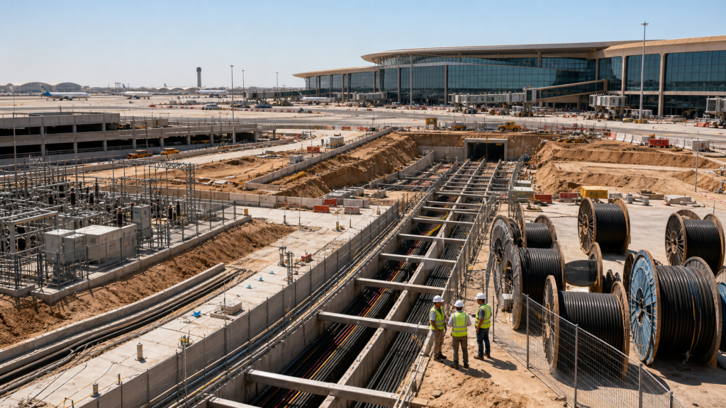
The three core cables are designed for distribution of electrical power with nominal voltage Uo/U ranging from 1.8/3KV to 26/35KV andfrequency 50Hz. They are suitable for installation mostly in power supply stations, indoors and in cable ducts, outdoors, underground and inwater as well as for installation on cable trays for industries, switchboards and power stations.


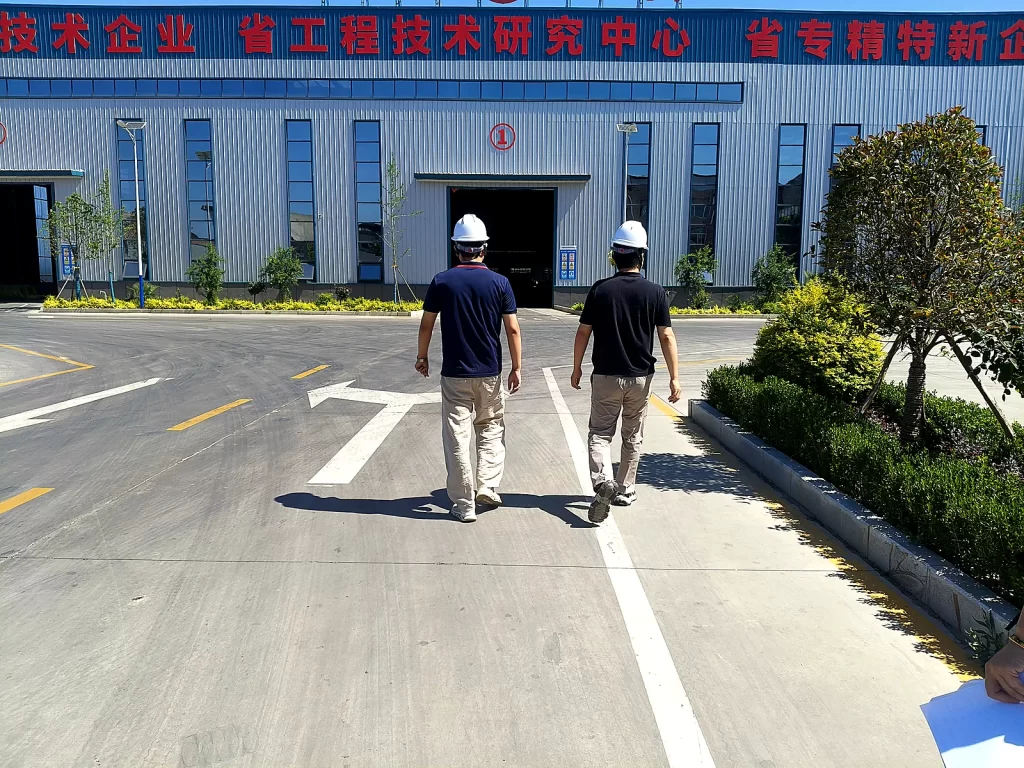
From Production to Delivery
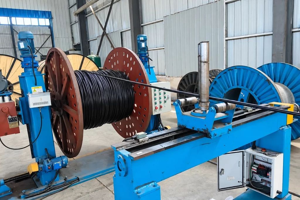
From raw material preparation to final shipmen, every stage is caretuly controled to ensure consistent conductor quality, reliable pertormance,and sae delivery. Our roduction,
inspection, packaging, and logistics processes are managed in accordance with applicable standards and project requirements.
Production
Stranded annealed copper conductors are insulated with XLPE, assembled into the required multicore configuration, optionally filled and bound with polyester tape, then covered with the specified black PVC sheath.

Inspection
Inspection focuses on conductor construction, insulation condition, core identification, sheath integrity, overall diameter, conductor resistance and test-voltage requirements against the approved technical schedule.
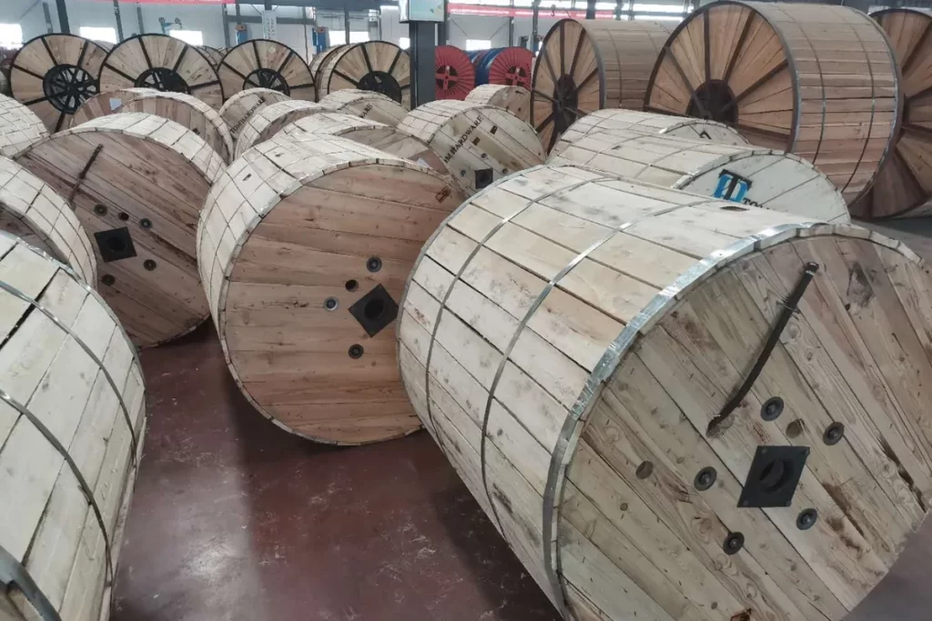
Packaging
Finished cable is wound on suitable drums according to ordered size, weight and length. Cable ends are protected and drum identification can include cable type, conductor size, core count, length and project reference.
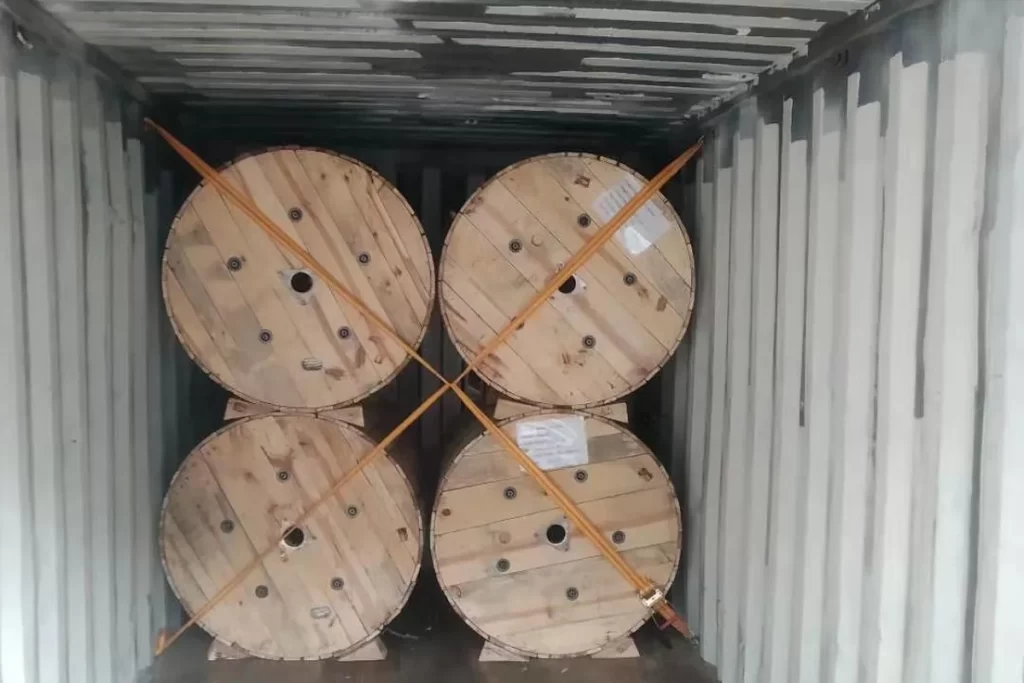
Shipping
Before shipment, cable drums and technical documents are checked against the order. Inspection records, identification data and requested test documentation can be prepared for the customer.
faq
What is the voltage range of these medium voltage three core cables?
These cables are designed for distribution of electrical power with a nominal voltage Uo/U ranging from 1.8/3kV up to 26/35kV, at a frequency of 50Hz.
What insulation types can I choose from?
Three insulation options are offered:
PVC (Polyvinyl Chloride) — for 1.8/3.6kV and 3.6/6kV cables, a cost-effective choice
XLPE (Cross-Linked Polyethylene) — high temperature rating (90°C), excellent electrical and mechanical properties
EPR/HEPR (Ethylene Propylene Rubber) — superior flexibility, cold resistance, and bending performance
Can I get the cable with armour? What types are available?
Yes, armour is available as an optional feature. Armour provides mechanical protection for direct burial or harsh installation environments. Options include steel wire armour (SWA) and steel tape armour, depending on your project requirements.
What oversheath materials are available?
The outer sheath is available in PVC, PE (Polyethylene), or LSZH (Low Smoke Zero Halogen) materials. LSZH is recommended for enclosed spaces and public areas due to its low smoke emission and zero halogen content in case of fire.
Can you manufacture custom cable specifications?
Yes, we offer extensive customization options to meet specific project requirements including:
- Special core configurations (e.g., 3+1E, 3+2E, 4+1E, custom multi-core)
- Custom outer sheath colors (red, blue, grey, etc. for identification)
- Special print marking with customer logo, project name, or custom text
- Low smoke zero halogen (LSZH) versions for special fire safety requirements
- UV-stabilized formulations for extreme outdoor exposure
- Oil-resistant and chemical-resistant sheath compounds
- Custom length drums and packaging
Custom orders typically require MOQ and may have slightly longer lead times. Contact our sales team with your specific requirements for a quote.
What is the typical lead time for orders?
Typical production lead times:
- Standard specifications (common sizes): 7-15 working days after order confirmation
- Custom specifications or special requirements: 15-25 working days
- Large volume orders: production schedule confirmed at time of order
We also maintain inventory of fast-moving standard sizes for immediate shipment. Transit time depends on destination port and shipping method. We can ship by sea (most cost-effective for large orders), air (urgent shipments), or rail (for Central Asian destinations).
Request for Free Consultation
Contact Information
Send us your cable requirements and our team will respond quickly with product recommendations, technical support and quotation details.