UB Clevis Links
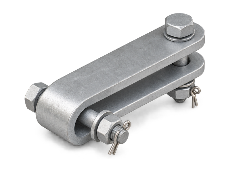
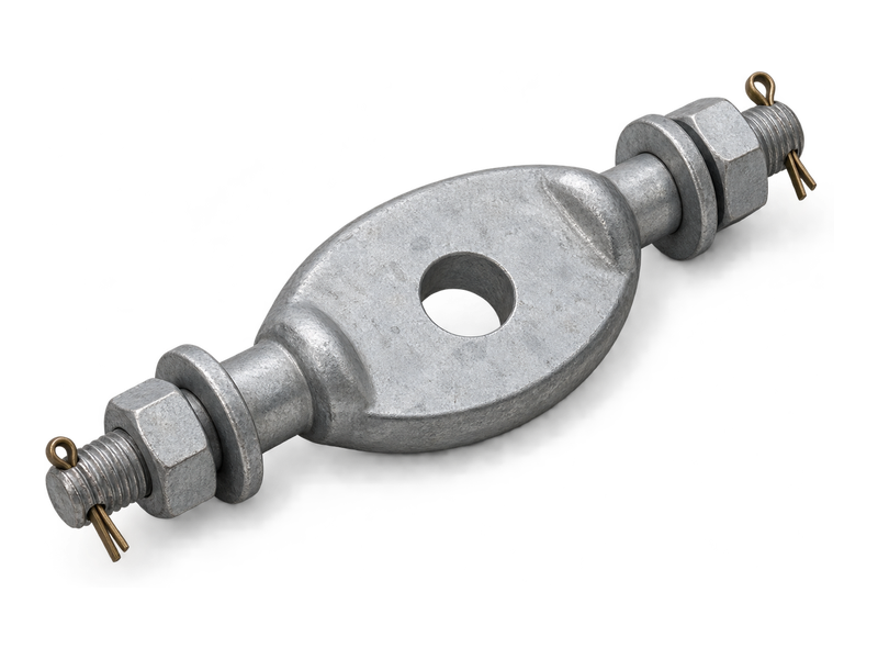
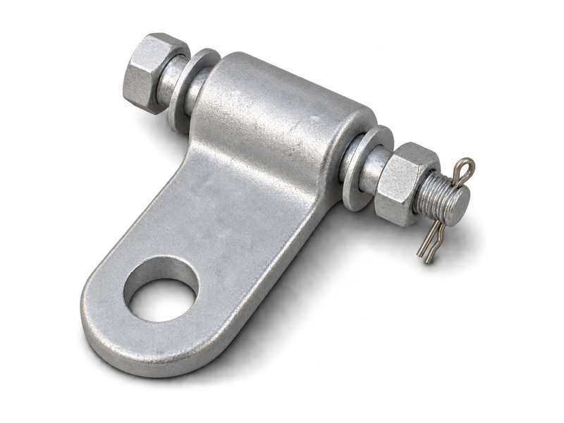
UB clevis links are bolted fittings with end connections arranged in perpendicular planes. Their upper body width and lower clevis opening define the interfaces within an insulator string. Standard, G and T variants have their own widths, bolt designations and centre distances. These details help buyers match the link to adjoining tongue connections and the available assembly space. Selection considers the complete end geometry and mechanical rating, especially when replacing a fitting in an existing overhead line hardware assembly.
Product Overview
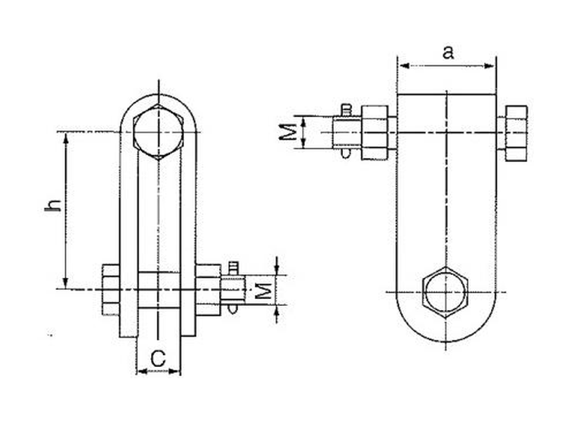
The UB body has two bolted connections with different orientations. The lower opening is marked C, the upper width a and the connection centre distance h. Model selection compares these dimensions with the mating fittings and checks the complete bolt and retention arrangement.
UB clevis links for overhead line hardware include standard and suffix variants with model-specific dimensions. The main parts are made from hot-dip galvanised steel, with stainless steel cotter pins. The specified body and bolt arrangement determine the connection geometry for each model.
Key Features
- Perpendicular bolt axes: The end arrangement accommodates adjoining connections in different planes.
- Separate width references: C and a describe different parts of the UB connection geometry.
- Suffix-specific dimensions: G and T variants have model-specific dimensions for matching the adjoining fittings.
- Bolted assembly: Two bolted joints link the UB body to the neighbouring fittings.
Product Applications
- Overhead line insulator strings: installed at a UB connection position between matching tongue-ended link fittings.
- Suspension and tension hardware assemblies: connects adjacent fittings where the specified layout uses the UB body form and perpendicular bolt axes.
Technical Specifications
Clevis Hinges (Type UB)
| Catalog No. | Dimensions (mm) | Rated Failure Load(kN) | Weight(kg) | |||
|---|---|---|---|---|---|---|
| C | M | h | a | |||
| UB-7 | 18 | 16 | 70 | 45 | 70 | 0.8 |
| UB-10 | 20 | 18 | 80 | 45 | 100 | 1.1 |
| UB-12 | 24 | 22 | 100 | 60 | 120 | 2.8 |
| UB-16 | 26 | 24 | 100 | 60 | 160 | 2.9 |
| UB-16G | 24 | 20 | 90 | 48 | 160 | 2.9 |
| UB-20 | 30 | 27 | 120 | 72 | 200 | 3.6 |
| UB-6-1 | 20 | 16 | 65 | 30 | 60 | 0.8 |
| UB-9.1 | 26 | 18 | 75 | 40 | 90 | 0.8 |
| UB-20T | 30 | 27 | 120 | 60 | 200 | 2.5 |
| UB-30T | 36 | 36 | 150 | 60 | 300 | 3.7 |
Request the Complete Data Sheet
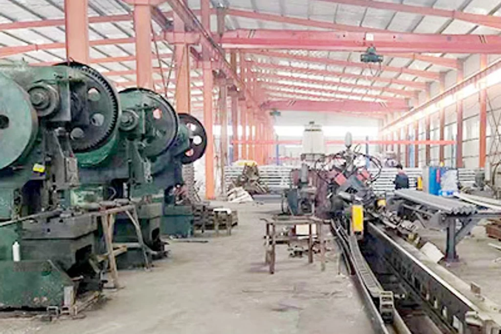
From Production to Delivery
From raw material preparation to final shipmen, every stage is caretuly controled to ensure consistent conductor quality, reliable pertormance,and sae delivery. Our roduction,
inspection, packaging, and logistics processes are managed in accordance with applicable standards and project requirements.
Production
The UB body is formed and its two connection positions are prepared to the selected model geometry. Surface treatment precedes assembly with the specified bolts and retaining parts.
Inspection
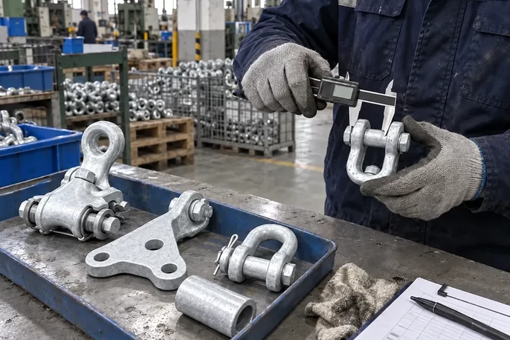
Inspection distinguishes the lower opening from the upper width and checks end orientation, centre distance and hardware fit. Mechanical evidence is associated with the specified model and assembly.
Packaging
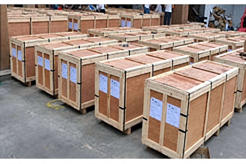
Labels preserve the full UB model suffix, while packing separates the fittings and retains each set of connecting hardware.
Shipping
Dispatch documentation records the model variants separately so that standard, G and T fittings can be allocated to their intended assembly positions.
Frequently Asked Questions
Are UB-16 and UB-16G interchangeable?
Drawing gives both models a rated failure load of 160 kN, but their connection dimensions differ. UB-16 lists C 26, M 24, h 100 and a 60, while UB-16G lists C 24, M 20, h 90 and a 48. The complete interfaces therefore need comparison.
Can a Z type clevis replace a UB fitting?
Both can use perpendicular end connections, but their body dimensions and connection widths differ. The replacement must match the adjoining fittings, assembly space and required mechanical performance.
What movement can UB clevis links accommodate?
Movement depends on the bolt joints and surrounding hardware. Connection dimensions alone do not establish an allowable rotation angle. Any articulation requirement belongs in the complete assembly design.
What information is needed to enquire about UB Clevis Links?
Provide the complete UB model including its suffix, required mechanical rating and quantity. Add C, a, h and M, the mating fitting details, the required movement within the assembly and the delivery destination.
Request for Free Consultation
Contact Information
Send us your cable requirements and our team will respond quickly with product recommendations, technical support and quotation details.