UL 1277 FR-XLPE LCT Shielded CPE Control Cable 600V
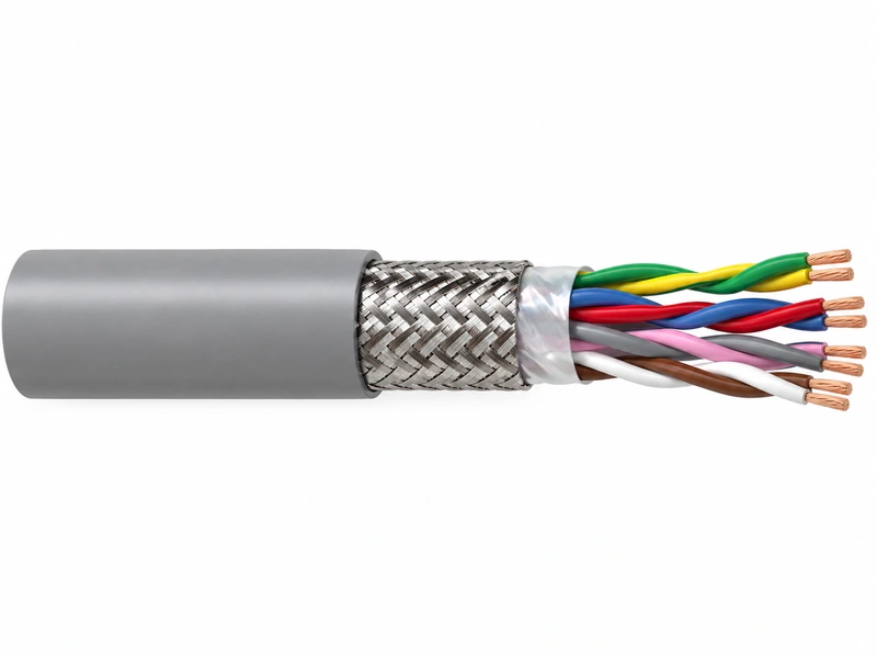
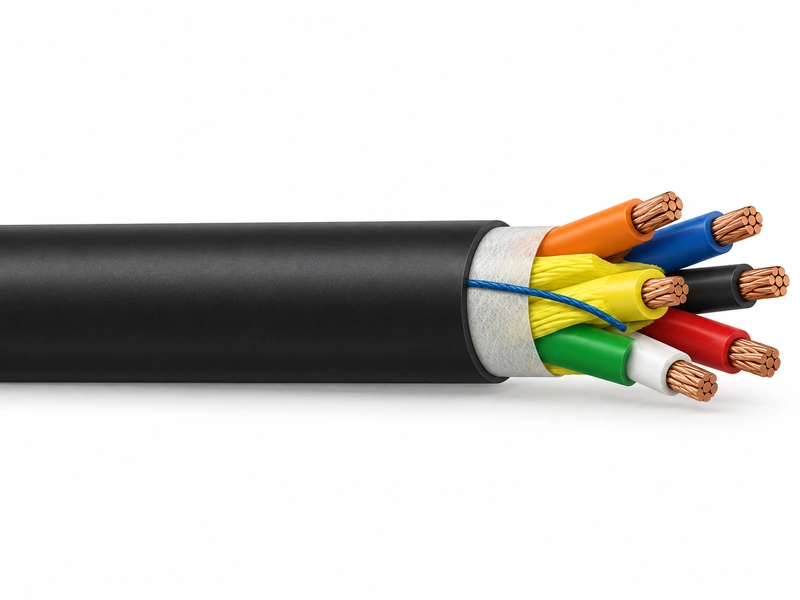
UL 1277 FR-XLPE LCT Shielded CPE Control Cable is a 600V multi-conductor industrial control cable with Class B compressed bare-copper conductors, flame-retardant XLPE insulation, a 5 mil LCT tape shield and a chlorinated-polyethylene (CPE) outer jacket. It is intended for wet and dry industrial control-cable routes where UL 1277 tray-cable construction, shielding and robust thermal performance are required.
PRODUCT OVERVIEW
The cable uses 7-strand Class B compressed bare-copper conductors insulated with 30 mil FR-XLPE. Polypropylene filler is used on constructions with five or fewer conductors, while cables with more than five conductors use a polyester flat-thread binder. A 5 mil LCT tape shield surrounds the cabled core, followed by a rip cord and an overall CPE jacket.
The product is rated 600V and is suited for wet and dry areas, conduits, ducts, troughs, trays, direct burial and aerial routes supported by a messenger. The source lists 90°C for normal operation, 130°C for emergency overload and 250°C for short-circuit conditions. UL-rated constructions may be used in Class I, II and III, Division 2 hazardous locations, while constructions with three or more conductors are stated as listed for exposed runs (TC-ER).
KEY FEATURES
- UL 1277 electrical power and control tray-cable product basis.
- 600V multi-conductor copper control cable.
- 7-strand Class B compressed bare-copper conductors.
- 30 mil flame-retardant XLPE insulation.
- 5 mil LCT tape shield.
- Chlorinated Polyethylene (CPE) outer jacket.
- Silicone-free construction.
- 90°C normal / 130°C emergency overload / 250°C short-circuit conductor temperatures stated in the source.
- Direct-burial, tray, duct, conduit, trough and messenger-supported aerial applications.
- UL-rated Class I, II and III, Division 2 use and TC-ER for qualifying constructions.
CABLE CONSTRUCTION
Conductor | 7-strand Class B compressed bare copper; source references ASTM B3 and ASTM B8 |
Insulation | Flame Retardant Cross Linked Polyethylene (FR-XLPE) |
Insulation Thickness | 30 mil stated for all listed cable sizes |
Filler | Polypropylene filler on cables with 5 or fewer conductors |
Binder | Polyester flat-thread binder tape on cables with more than 5 conductors |
Shield | LCT tape shield, 5 mil |
Rip Cord | Included for ease of jacket removal |
Overall Jacket | Chlorinated Polyethylene (CPE) |
Voltage Rating | 600V |
Silicone Free | Yes, stated in the source |
UL 1277 TYPE TC DESIGN FOCUS
Focus | How It Relates to This Product |
Complete Multiconductor Cable | Compressed copper conductors, FR-XLPE insulation, filler/binder, LCT tape shield and CPE jacket |
Shielded Construction | Source specifies a 5 mil LCT tape shield around the cabled core |
Tray / Raceway Installations | Source lists trays, troughs, conduits and ducts |
Direct Burial | Stated in the application data |
Wet / Dry Locations | Both are stated with 90°C normal operation |
Aerial Use | Messenger-supported aerial installation is stated |
Hazardous Locations | UL-rated constructions may be used in Class I, II and III, Division 2 locations |
TC-ER | UL-rated constructions with 3 or more conductors are stated as listed for exposed runs |
WHY LCT SHIELDING?
The defining difference between this construction and an unshielded control cable is the 5 mil LCT tape shield. The shield creates a dedicated metallic layer around the multicore assembly, making this product appropriate where the project specification calls for a shielded control-cable construction.
The source does not state the LCT material composition, shield coverage percentage, drain-wire construction or a specific grounding method. Those details should therefore be confirmed with the manufacturer whenever the project has a defined EMC, shield-termination or grounding requirement.
SHIELDED VS UNSHIELDED FR-XLPE / CPE CONTROL CABLE
Feature | Shielded Type | Unscreened Type |
Metallic Shield | 5 mil LCT tape shield | No shield layer |
Primary Selection Reason | Projects requiring a shielded control-cable construction | General control circuits where overall shielding is not required |
Cable Build | Additional shield layer between core assembly and outer jacket | Core assembly followed by outer jacket |
Engineering Review | Shield material / termination / grounding requirements should be confirmed | Routing and interference conditions should be checked without an overall screen |
PRODUCT APPLICATIONS
- Industrial control circuits requiring a shielded 600V multi-conductor tray cable.
- Wet and dry areas.
- Conduits, ducts, troughs and trays.
- Direct-burial installations.
- Aerial routes supported by a messenger.
- Projects requiring shielded FR-XLPE / CPE control cable construction.
- UL-rated Class I, II and III, Division 2 hazardous-location applications.
- TC-ER exposed-run installations for qualifying UL-rated constructions with 3 or more conductors.
Physical and electrical data reproduced from the supplied product schedule. Units are retained as provided in the source. How to read this table: the schedule combines conductor diameter, insulation and jacket thickness, approximate overall diameter, copper weight, approximate cable weight, DC resistance, AC resistance at 90°C, minimum bending radius and allowable ampacity at 60°C, 75°C and 90°C. The 10 AWG schedule includes two separate 4-core entries with different dimensions and weights; both are retained exactly as supplied and should be confirmed before quotation.
| AWG | Cores | Cond. Dia. in | Insul. mil | Jacket mil | OD in | Cu Wt lb/kft | Cable Wt lb/kft | DC R Ω/kft | AC R @90°C Ω/kft | Min Bend in | Amp 60°C | Amp 75°C | Amp 90°C |
|---|---|---|---|---|---|---|---|---|---|---|---|---|---|
| 10 | 2 | 0.111 | 30 | 45 | 0.431 | 65 | 124 | 1.040 | 1.300 | 1.7 | 30 | 30 | 30 |
| 10 | 3 | 0.111 | 30 | 45 | 0.459 | 97 | 165 | 1.040 | 1.300 | 1.8 | 30 | 30 | 30 |
| 10 | 4 | 0.111 | 30 | 60 | 0.502 | 178 | 210 | 1.040 | 1.300 | 4.5 | 24 | 28 | 30 |
| 10 | 4 | 0.111 | 30 | 60 | 0.641 | 174 | 300 | 1.040 | 1.300 | 4.4 | 24 | 28 | 30 |
| 10 | 5 | 0.111 | 30 | 60 | 0.581 | 162 | 273 | 1.040 | 1.300 | 2.3 | 24 | 28 | 30 |
| 10 | 6 | 0.111 | 30 | 60 | 0.632 | 194 | 323 | 1.040 | 1.300 | 2.5 | 24 | 28 | 30 |
| 10 | 7 | 0.111 | 30 | 60 | 0.632 | 227 | 358 | 1.040 | 1.300 | 2.5 | 21 | 24 | 28 |
| 10 | 8 | 0.111 | 30 | 60 | 0.685 | 259 | 410 | 1.040 | 1.300 | 2.7 | 21 | 24 | 28 |
| 10 | 9 | 0.111 | 30 | 60 | 0.736 | 291 | 461 | 1.040 | 1.300 | 2.9 | 21 | 24 | 28 |
| 10 | 10 | 0.111 | 30 | 60 | 0.803 | 324 | 519 | 1.040 | 1.300 | 3.2 | 15 | 17 | 20 |
| 10 | 12 | 0.111 | 30 | 80 | 0.984 | 389 | 600 | 1.040 | 1.300 | 3.3 | 15 | 17 | 20 |
| 10 | 15 | 0.111 | 30 | 80 | 0.964 | 486 | 777 | 1.040 | 1.300 | 3.9 | 15 | 17 | 20 |
| 10 | 19 | 0.111 | 30 | 80 | 1.014 | 615 | 941 | 1.040 | 1.300 | 5.1 | 15 | 17 | 20 |
| 10 | 20 | 0.111 | 30 | 80 | 1.067 | 648 | 1001 | 1.040 | 1.300 | 5.3 | 15 | 17 | 20 |
| 10 | 25 | 0.111 | 30 | 80 | 1.184 | 810 | 1236 | 1.040 | 1.300 | 5.9 | 13 | 15 | 18 |
| 10 | 30 | 0.111 | 30 | 80 | 1.254 | 971 | 1450 | 1.040 | 1.300 | 6.3 | 13 | 15 | 18 |
Physical and electrical data reproduced from the supplied product schedule. Units are retained as provided in the source. How to read this table: the schedule combines conductor diameter, insulation and jacket thickness, approximate overall diameter, copper weight, approximate cable weight, DC resistance, AC resistance at 90°C, minimum bending radius and allowable ampacity at 60°C, 75°C and 90°C. The 10 AWG schedule includes two separate 4-core entries with different dimensions and weights; both are retained exactly as supplied and should be confirmed before quotation.
| AWG | Cores | Cond. Dia. in | Insul. mil | Jacket mil | OD in | Cu Wt lb/kft | Cable Wt lb/kft | DC R Ω/kft | AC R @90°C Ω/kft | Min Bend in | Amp 60°C | Amp 75°C | Amp 90°C |
|---|---|---|---|---|---|---|---|---|---|---|---|---|---|
| 12 | 2 | 0.087 | 30 | 45 | 0.384 | 41 | 90 | 1.660 | 2.075 | 1.5 | 20 | 20 | 20 |
| 12 | 3 | 0.087 | 30 | 45 | 0.408 | 61 | 118 | 1.660 | 2.075 | 1.6 | 20 | 20 | 20 |
| 12 | 4 | 0.087 | 30 | 45 | 0.445 | 81 | 148 | 1.660 | 2.075 | 1.8 | 16 | 20 | 20 |
| 12 | 5 | 0.087 | 30 | 45 | 0.487 | 102 | 181 | 1.660 | 2.075 | 1.9 | 16 | 20 | 20 |
| 12 | 6 | 0.087 | 30 | 45 | 0.532 | 122 | 214 | 1.660 | 2.075 | 2.1 | 16 | 20 | 20 |
| 12 | 7 | 0.087 | 30 | 45 | 0.532 | 143 | 237 | 1.660 | 2.075 | 2.1 | 14 | 17 | 20 |
| 12 | 8 | 0.087 | 30 | 60 | 0.607 | 163 | 288 | 1.660 | 2.075 | 2.4 | 14 | 17 | 20 |
| 12 | 9 | 0.087 | 30 | 60 | 0.661 | 183 | 324 | 1.660 | 2.075 | 2.6 | 14 | 17 | 20 |
| 12 | 10 | 0.087 | 30 | 60 | 0.709 | 204 | 365 | 1.660 | 2.075 | 2.8 | 10 | 12 | 15 |
| 12 | 12 | 0.087 | 30 | 60 | 0.732 | 244 | 419 | 1.660 | 2.075 | 2.9 | 10 | 12 | 15 |
| 12 | 15 | 0.087 | 30 | 60 | 0.813 | 305 | 516 | 1.660 | 2.075 | 3.3 | 10 | 12 | 15 |
| 12 | 19 | 0.087 | 30 | 80 | 0.896 | 387 | 657 | 1.660 | 2.075 | 3.6 | 10 | 12 | 15 |
| 12 | 20 | 0.087 | 30 | 80 | 0.942 | 407 | 699 | 1.660 | 2.075 | 3.8 | 10 | 12 | 15 |
| 12 | 25 | 0.087 | 30 | 80 | 1.043 | 509 | 860 | 1.660 | 2.075 | 5.2 | 9 | 11 | 13 |
| 12 | 30 | 0.087 | 30 | 80 | 1.104 | 611 | 1005 | 1.660 | 2.075 | 5.5 | 9 | 11 | 13 |
| 12 | 37 | 0.087 | 30 | 80 | 1.191 | 753 | 1211 | 1.660 | 2.075 | 6.0 | 8 | 10 | 12 |
Physical and electrical data reproduced from the supplied product schedule. Units are retained as provided in the source. How to read this table: the schedule combines conductor diameter, insulation and jacket thickness, approximate overall diameter, copper weight, approximate cable weight, DC resistance, AC resistance at 90°C, minimum bending radius and allowable ampacity at 60°C, 75°C and 90°C. The 10 AWG schedule includes two separate 4-core entries with different dimensions and weights; both are retained exactly as supplied and should be confirmed before quotation.
| AWG | Cores | Cond. Dia. in | Insul. mil | Jacket mil | OD in | Cu Wt lb/kft | Cable Wt lb/kft | DC R Ω/kft | AC R @90°C Ω/kft | Min Bend in | Amp 60°C | Amp 75°C | Amp 90°C |
|---|---|---|---|---|---|---|---|---|---|---|---|---|---|
| 14 | 2 | 0.070 | 30 | 45 | 0.349 | 26 | 68 | 2.630 | 3.288 | 1.4 | 15 | 15 | 15 |
| 14 | 3 | 0.070 | 30 | 45 | 0.370 | 38 | 87 | 2.630 | 3.288 | 1.5 | 15 | 15 | 15 |
| 14 | 4 | 0.070 | 30 | 45 | 0.403 | 51 | 109 | 2.630 | 3.288 | 1.6 | 14 | 15 | 15 |
| 14 | 5 | 0.070 | 30 | 45 | 0.440 | 64 | 132 | 2.630 | 3.288 | 1.8 | 14 | 15 | 15 |
| 14 | 6 | 0.070 | 30 | 45 | 0.479 | 77 | 155 | 2.630 | 3.288 | 1.9 | 14 | 15 | 15 |
| 14 | 7 | 0.070 | 30 | 45 | 0.479 | 90 | 171 | 2.630 | 3.288 | 1.9 | 12 | 15 | 15 |
| 14 | 8 | 0.070 | 30 | 45 | 0.519 | 102 | 195 | 2.630 | 3.288 | 2.1 | 12 | 15 | 15 |
| 14 | 9 | 0.070 | 30 | 60 | 0.588 | 115 | 236 | 2.630 | 3.288 | 2.4 | 12 | 15 | 15 |
| 14 | 10 | 0.070 | 30 | 60 | 0.638 | 128 | 266 | 2.630 | 3.288 | 2.6 | 9 | 11 | 12 |
| 14 | 12 | 0.070 | 30 | 60 | 0.669 | 154 | 303 | 2.630 | 3.288 | 2.6 | 9 | 11 | 12 |
| 14 | 15 | 0.070 | 30 | 60 | 0.730 | 192 | 371 | 2.630 | 3.288 | 2.9 | 9 | 11 | 12 |
| 14 | 19 | 0.070 | 30 | 60 | 0.768 | 243 | 446 | 2.630 | 3.288 | 3.1 | 9 | 11 | 12 |
| 14 | 20 | 0.070 | 30 | 60 | 0.808 | 256 | 475 | 2.630 | 3.288 | 3.2 | 9 | 11 | 12 |
| 14 | 25 | 0.070 | 30 | 80 | 0.937 | 320 | 619 | 2.630 | 3.288 | 3.7 | 8 | 9 | 11 |
| 14 | 30 | 0.070 | 30 | 80 | 0.991 | 384 | 719 | 2.630 | 3.288 | 4.0 | 8 | 9 | 11 |
| 14 | 37 | 0.070 | 30 | 80 | 1.067 | 474 | 862 | 2.630 | 3.288 | 5.3 | 7 | 8 | 10 |
Request the Complete Data Sheet
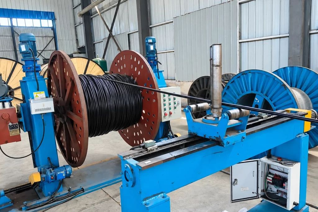
From Production to Delivery
From raw material preparation to final shipmen, every stage is caretuly controled to ensure consistent conductor quality, reliable pertormance,and sae delivery. Our roduction,
inspection, packaging, and logistics processes are managed in accordance with applicable standards and project requirements.
Production
Class B compressed bare-copper conductors are prepared, insulated with FR-XLPE, assembled with polypropylene filler or polyester binder according to core count, wrapped with the specified 5 mil LCT tape shield, fitted with the rip cord and finished with the CPE jacket.

Inspection
Inspection focuses on conductor construction, insulation/jacket thickness, shield application, overall diameter, conductor and cable weight, DC/AC resistance, bending-radius data, cable marking and project-specified documentation.
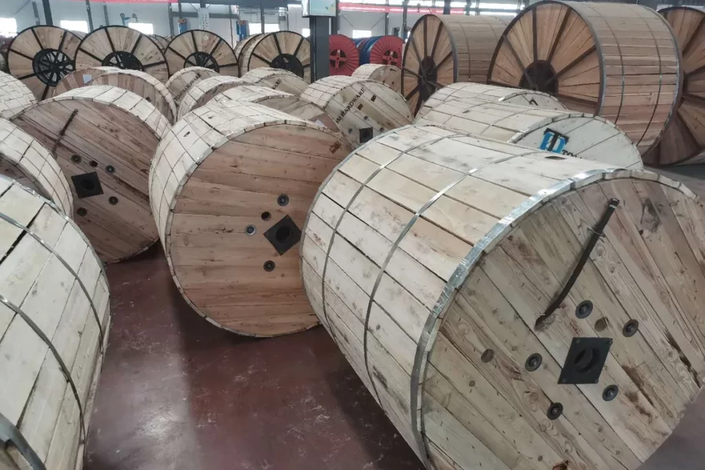
Packaging
Finished cable is wound on reels or drums suitable for its diameter, weight and ordered length. Product identification can include conductor size, core count, standard reference, length and project number.
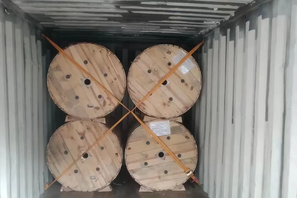
Shipping
Before shipment, cable marking, packing, inspection records and requested standard/test documents are checked against the order and project approval requirements.
Frequently Asked Questions
When should I choose this shielded version instead of the unshielded FR-XLPE/CPE control cable?
Choose the shielded version when the project specification calls for an overall shielded control-cable construction or when the engineering design requires a metallic screen around the multicore assembly. The source specifies a 5 mil LCT tape shield. If shielding is not required, the unshielded construction may be simpler.
What details about the LCT shield should be confirmed before ordering?
The source states only that the cable has a 5 mil LCT tape shield. It does not define the tape material, coverage, drain wire or grounding method. If the project has specific EMC, continuity, grounding or termination requirements, those items should be confirmed with the manufacturer before quotation.
What should I verify if TC-ER is required?
The source states that UL-rated constructions with three or more conductors are listed for exposed runs. Confirm that the exact conductor size and core count being supplied carries the required TC-ER marking/listing rather than relying only on the family description.
Can this cable be used in hazardous locations?
The source states that UL-rated constructions can be used in Class I, II and III, Division 2 hazardous locations. The complete installation still depends on cable marking, fittings, seals, wiring method and the governing NEC/project requirements.
How should the 60°C, 75°C and 90°C ampacity columns be used?
Use the column appropriate to the permitted conductor/termination temperature in the project design, then apply any code-required derating for ambient temperature, grouping and installation conditions. The listed values are product data, not a substitute for the governing electrical-code calculation.
What products do you supply for the power cable industry?
We provide a wide range of cable materials and electrical products, including aluminum conductors, aluminum rods, aluminum wires, overhead conductors, medium and low voltage power cables, cable insulation materials, filling materials, shielding materials, and cable manufacturing consumables.We provide customized solutions according to different cable manufacturing requirements.
Request for Free Consultation
Contact Information
Send us your cable requirements and our team will respond quickly with product recommendations, technical support and quotation details.